Hub - Rear - LH (Remove and Replace)
 Correction code
31030702
0.48
NOTE: Unless otherwise explicitly
stated in the procedure, the above correction code and FRT reflect all of the work
required to perform this procedure, including the linked procedures. Do not stack correction codes unless
explicitly told to do so.
NOTE: See Flat Rate
Times to learn more about FRTs and how they are created.
NOTE: See Personal Protection to make sure wearing proper PPE when
performing the below procedure. NOTE: See Ergonomic Precautions for safe and healthy working
practices.
Correction code
31030702
0.48
NOTE: Unless otherwise explicitly
stated in the procedure, the above correction code and FRT reflect all of the work
required to perform this procedure, including the linked procedures. Do not stack correction codes unless
explicitly told to do so.
NOTE: See Flat Rate
Times to learn more about FRTs and how they are created.
NOTE: See Personal Protection to make sure wearing proper PPE when
performing the below procedure. NOTE: See Ergonomic Precautions for safe and healthy working
practices.
- 2026-02-19: Clarified that lubricant on splines can cause the hub not to seat and can introduce contamination.
- 2025-11-25: Added note to remove knuckle if hub is seized to knuckle.
- 2024-01-19: Updated EPB Service Mode reference.
- 2023-11-13: Changed the step order of removing the brake rotor bolt due to the hub puller tool is updated.
Torque Specifications
| Description | Torque Value | Recommended Tools | Reuse/Replace | Notes |
|---|---|---|---|---|
| Bolts that attach the LH rear hub and bearing to the LH rear knuckle |
 85 Nm (62.7 lbs-ft) |
|
Reuse | |
| Bolt that attaches the LH rear rotor to the LH rear hub |
5 Nm (3.7 lbs-ft) |
|
Reuse | |
| Bolts that attach the LH rear caliper to the LH rear knuckle |
83 Nm (61.2 lbs-ft) |
|
Replace | |
| Nut that attaches the LH rear halfshaft to the LH rear hub assembly |
 300 Nm (221.2 lbs-ft) |
|
Replace |
Remove
- Raise and support the vehicle. See Raise Vehicle - 2 Post Lift.
- Open the LH front door and fully lower the LH front window.
- Enable the EPB Service Mode. See Parking Brake - Caliper - Rear - LH (Release).
- If equipped, remove the LH rear wheel center cap. See Cap - Wheel (Remove and Replace).
-
Loosen the LH rear wheel lug
nuts.
CAUTIONUse only hand tools to remove or install the fasteners. Do not use impact or power tools.CAUTIONUse a 6 point socket. Do not use a 12 point socket or a specialty socket.
-
Loosen the LH rear drive
unit halfshaft nut.
TIpUse of the following tool(s) is recommended:
- Long Breaker Bar
- 32 mm deep impact socket
- Remove the LH rear wheel. See Wheel Assembly (Remove and Install).
-
Remove and discard the bolts
that attach the LH rear caliper to the LH rear knuckle, remove the caliper
from the knuckle, and allow the caliper to hang from an S-hook.
TIpUse of the following tool(s) is recommended:
- External Torx E18
-
Remove and discard the LH
rear halfshaft nut and washer.
TIpUse of the following tool(s) is recommended:
- 32 mm deep impact socket
-
Position the hub puller onto
the LH rear hub assembly, and then secure the puller with the wheel lug nuts
(x2) and hub puller washers (x2).
TIpUse of the following tool(s) is recommended:
- 21 mm socket
- Flex head ratchet/flex head torque wrench
- 6 in extension
-
Rotate the hub puller counterclockwise to free the LH rear halfshaft from
the LH rear hub splines.
TIpUse of the following tool(s) is recommended:
- 17 mm deep socket
- Remove the hub puller tool from the LH rear hub assembly.
-
Remove the bolt that attaches the LH
rear brake rotor to the hub, but do not remove the rotor at this time.5 Nm (3.7 lbs-ft)TIpUse of the following tool(s) is recommended:
- 10 mm socket
-
Remove the LH rear brake
rotor from the vehicle.
-
Remove the bolts that attach
the LH rear hub to the knuckle, and then remove the hub from the
vehicle.
TIpUse of the following tool(s) is recommended:
- 18 mm socket
CAUTIONIf the hub is seized to the knuckle and cannot be removed without damaging the half-shaft boot, remove the knuckle, then remove the hub screws.Figure 1. Halfshaft hidden for clarity
Install
-
Inspect the tone ring on the
LH rear hub prior to installation.
CAUTIONReplace the hub if tone ring shows signs damage.
Figure 2. Bad tone ring Figure 3. Good tone ring -
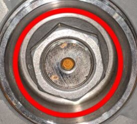
Apply approximately 1 gram
of Molykote M-77 Lubricant Paste only to the hub
mating face on the outboard side of the LH rear drive unit halfshaft.
CAUTIONDo not apply any lubricant to the halfshaft splines. Lubrication on the splines can prevent the hub from fully seating and can introduce contamination. If lubricant is mistakenly applied, wipe the splines clean with a shop towel.
Figure 4. Lubricate the area highlighted red -
Position the LH rear
halfshaft into the LH rear hub assembly, and then install the bolts that
attach the LH rear hub and bearing to the LH rear knuckle.85 Nm (62.7 lbs-ft)TIpUse of the following tool(s) is recommended:
- 18 mm socket
Figure 5. Halfshaft hidden for clarity -
Install a new nut and washer that attach the LH rear halfshaft to the LH
rear hub assembly.
NoteNut will be torqued at a later step.TIpUse of the following tool(s) is recommended:
- 32 mm deep impact socket
-
Position the LH rear brake
rotor onto the LH rear hub, and then install the bolt that attaches the
rotor to the hub.5 Nm (3.7 lbs-ft)TIpUse of the following tool(s) is recommended:
- 10 mm socket
-
Position the LH rear caliper
onto the LH rear knuckle, and then install new bolts that attach the caliper
to the knuckle.83 Nm (61.2 lbs-ft)TIpUse of the following tool(s) is recommended:
- External Torx E18
- Install the LH rear wheel. See Wheel Assembly (Remove and Install).
-
Torque the LH rear halfshaft
nut.300 Nm (221.2 lbs-ft)TIpUse of the following tool(s) is recommended:
- 32 mm deep impact socket
- If equipped, install the LH front wheel center cap. See Cap - Wheel (Remove and Replace).
- On the vehicle touchscreen, press and hold the park button to release EPB service mode.
- Close the LH front door and raise the LH front window.
- Remove the vehicle from the lift.
- Refer to the Alignment Requirement tables to determine whether an EPAS alignment check (EC) or four wheel alignment check (AC) is necessary. If performed, add the alignment check/adjust correction code as a separate activity to the SV. See Alignment Requirement - Suspension.