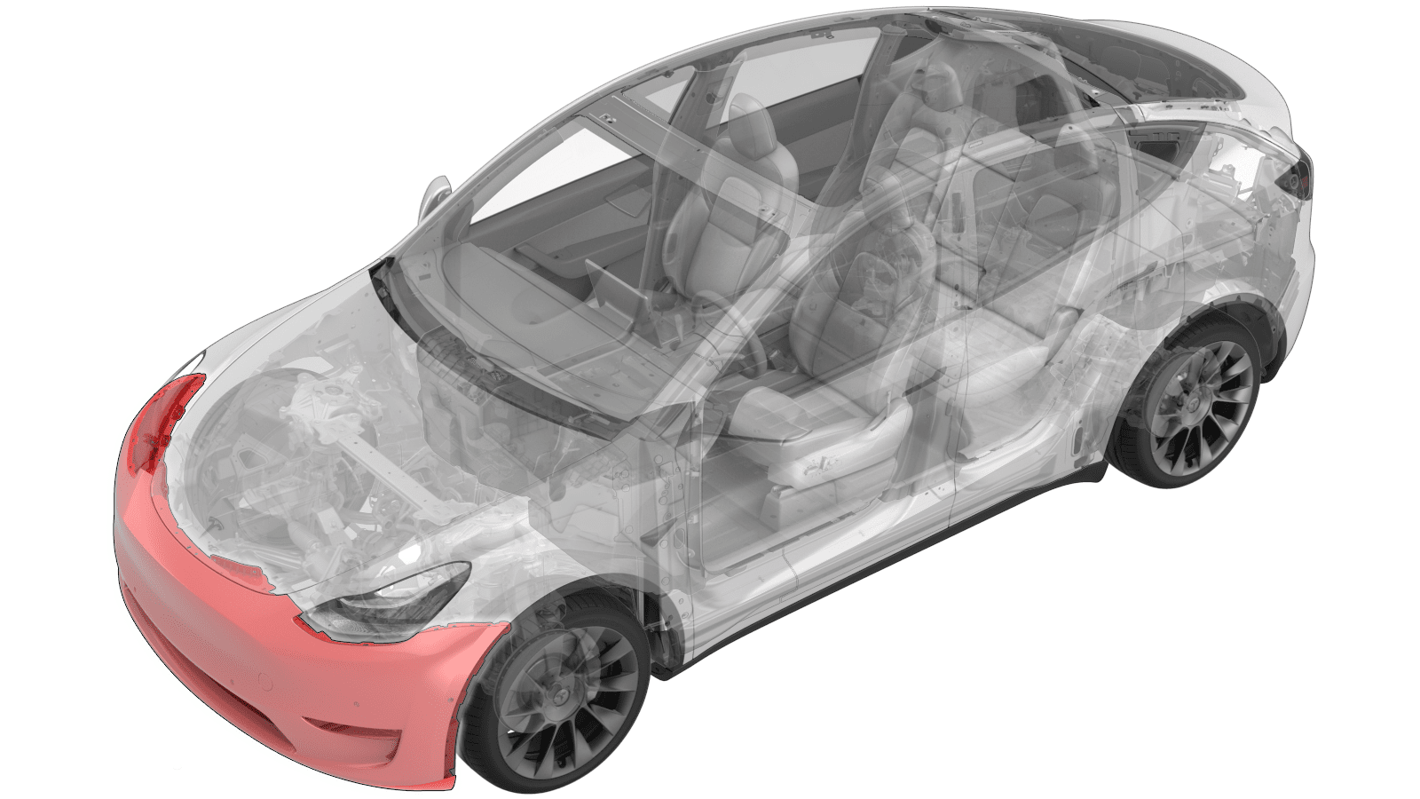
Fascia - Front (Remove and Install)
 Correction code
10011001
0.48
NOTE: Unless otherwise explicitly
stated in the procedure, the above correction code and FRT reflect all of the work
required to perform this procedure, including the linked procedures. Do not stack correction codes unless
explicitly told to do so.
NOTE: See Flat Rate
Times to learn more about FRTs and how they are created.
NOTE: See Personal Protection to make sure wearing proper PPE when
performing the below procedure. NOTE: See Ergonomic Precautions for safe and healthy working
practices.
Correction code
10011001
0.48
NOTE: Unless otherwise explicitly
stated in the procedure, the above correction code and FRT reflect all of the work
required to perform this procedure, including the linked procedures. Do not stack correction codes unless
explicitly told to do so.
NOTE: See Flat Rate
Times to learn more about FRTs and how they are created.
NOTE: See Personal Protection to make sure wearing proper PPE when
performing the below procedure. NOTE: See Ergonomic Precautions for safe and healthy working
practices.
Torque Specifications
| Description | Torque Value | Recommended Tools | Reuse/Replace | Notes |
|---|---|---|---|---|
| Bolts that attach the top of the front fascia to the vehicle |
 4 Nm (2.9 lbs-ft) |
|
Reuse | |
| Bolt that attaches the LH corner of the front fascia to the fender |
4 Nm (2.9 lbs-ft) |
|
Reuse |
Remove
- Open the LH front door.
- Remove the rear underhood apron. See Underhood Apron - Rear (Remove and Replace).
- Remove the underhood storage unit. See Underhood Storage Unit (Remove and Replace).
-
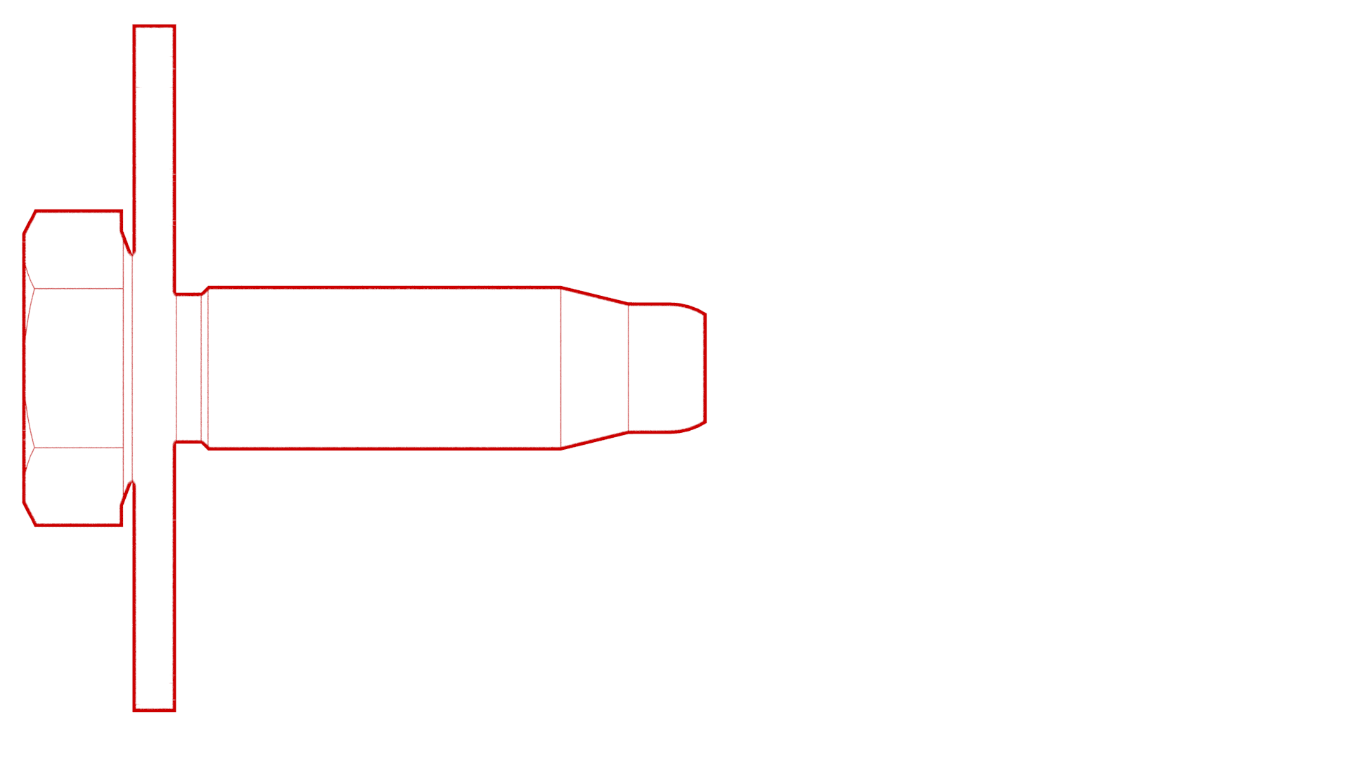
Remove the bolts that attach
the top of the front fascia to the vehicle.4 Nm (2.9 lbs-ft)TIpUse of the following tool(s) is recommended:
- 10 mm socket
- Remove the LH front fender garnish. See Garnish - Fender - Front - LH (Remove and Replace)
-
Release the clips (x4) that
attach the front portion of the LH front wheel arch liners to the vehicle,
and then move the wheel arch liner aside to perform the following
steps.
Figure 1. LH shown; RH similar -
Remove the bolt that
attaches the LH corner of the front fascia to the fender.4 Nm (2.9 lbs-ft)TIpUse of the following tool(s) is recommended:
- 10 mm socket
Figure 2. LH shown; RH similar - Repeat step 5 through step 7 for the RH side of the vehicle.
-
Remove the bolts that attach the front of the front aero shield to the
vehicle.
 5 Nm (3.7 lbs-ft)
 -
Partially release the RH side of the front fascia.
-
Disconnect the electrical
connector from the front fascia in the RH wheel well.
-
If present, release the clip
that attaches the electrical harness to the pedestrian warning speaker
assembly.
-
If present, slide the
locking tab away from the connector, and then press down on the locking tab
to disconnect the connector from the pedestrian warning speaker
assembly.
-
With an assistant, release
the LH side of the front fascia, and then carefully pull the fascia up and
forward to remove it from the vehicle. Place the fascia on a padded
surface.
CAUTIONCarefully release the tabs that attach the lower headlight bracket to the front fascia, otherwise the tabs can be broken.WarningThe corners of the ankle catcher are very sharp and might cause personal injury.
LH ankle catcher corner shown; RH corner similar
Install
Installation procedure is the reverse of removal, except for the following:
- Align the fascia to the fender before tightening the bolts that attach the fascia to the fender.
- Perform a radar sensor calibration only if the front radar sensor likely moved outside of its calibration tolerance (contact while removing the fascia, etc.). See Sensor - Radar - Front (Calibration).NoteIf radar sensor calibration is required, add the correction code separately.
- Apply a thin bead of Loctite 222 to the threads of the bolts (x4) that attach the front aero shield panel to the vehicle.