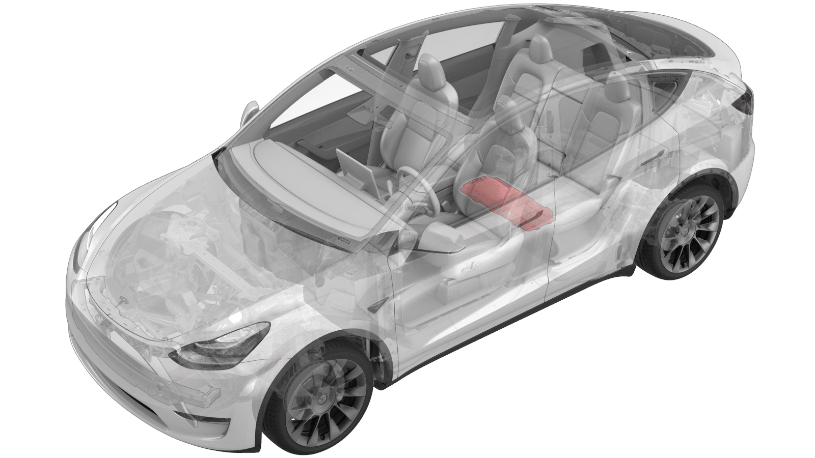
Power Conversion System (Non-Structural Pack) (Remove and Install)
 Correction code
16301001
2.34
NOTE: Unless otherwise explicitly
stated in the procedure, the above correction code and FRT reflect all of the work
required to perform this procedure, including the linked procedures. Do not stack correction codes unless
explicitly told to do so.
NOTE: See Flat Rate
Times to learn more about FRTs and how they are created.
NOTE: See Personal Protection to make sure wearing proper PPE when
performing the below procedure. NOTE: See Ergonomic Precautions for safe and healthy working
practices.
Correction code
16301001
2.34
NOTE: Unless otherwise explicitly
stated in the procedure, the above correction code and FRT reflect all of the work
required to perform this procedure, including the linked procedures. Do not stack correction codes unless
explicitly told to do so.
NOTE: See Flat Rate
Times to learn more about FRTs and how they are created.
NOTE: See Personal Protection to make sure wearing proper PPE when
performing the below procedure. NOTE: See Ergonomic Precautions for safe and healthy working
practices.
Equipment:
- 1111868-00-B Connector Removal, Coolant, PCS, M3
- 1135762-00-A Kit, Svc Plug, Cooling Hose, Model 3
- 1114917-00-A Tool, Vacuum Cup, 3" x 6" (Qty 2)
- 1076927-00-A Resistance meter, micro ohm, Hioki RM 3548
- 2026-03-11: Moved step to remove pyro disconnect to immediately after removing the ancillary bay cover.
Only
technicians who have completed all required certification courses are permitted to
perform this procedure. Tesla recommends third party service provider technicians
undergo equivalent training before performing this procedure. For more information on
Tesla Technician requirements, or descriptions of the subject matter for third parties,
see HV Certification Requirements. Proper personal protective equipment (PPE) and insulating HV
gloves with a minimum rating of class 0 (1000V) must
be worn at all times a high voltage cable, busbar, or fitting is handled. Refer to Tech Note TN-15-92-003, High Voltage Awareness
Care Points
for additional safety
information.
Torque Specifications
| Description | Torque Value | Recommended Tools | Reuse/Replace | Notes |
|---|---|---|---|---|
| Bolts that attach the power conversion system to the HV battery |
 18 Nm (13.3 lbs-ft) |
|
Reuse | Upon installation, mark each bolt with a paint pen |
Remove
-
Place the vehicle on the 2-post
lift.
TIpEnsure the vehicle is not charging.
- Open all doors and lower all windows.
- Remove the RH 2nd row seat back. See Seat Back - 2nd Row - RH (Remove and Replace).
- Remove the LH 2nd row seat back. See Seat Back - 2nd Row - LH (Remove and Replace).
- Perform Vehicle HV Disablement Procedure. See Vehicle HV Disablement Procedure.
- Remove the ancillary bay cover. See Cover - Ancillary Bay (Remove and Install).
- Remove the pyrotechnic battery disconnect. See Pyrotechnic Battery Disconnect (Remove and Replace).
-
Inspect the ancillary bay for any
missing insulators. Install the missing insulators before continuing.
NoteThe number of bolts on newer vehicles may vary.
-
Reinstall the logic connector cap onto
the high voltage controller (HVC) connector.
-
Raise the high voltage controller
vertically, and then restrain the controller with a bungee strap.
- Remove the HV insulating gloves.
- Drain the coolant from the power conversion system. See Ancillary Bay Coolant (Drain and Refill).
- Lower the vehicle fully.
- Inspect the HV insulating gloves, then put on the HV insulating gloves and leather over gloves.
- Position absorbent sheets below and around the power conversion system (PCS) coolant inlet and outlet hoses to avoid excess coolant dripping.
-
Use the coolant connector removal tool
to release the clips that attach the coolant input tube to the power conversion system,
and remove the tube from the power conversion system. See Tube - Input - Coolant - Power Conversion System (Remove and Replace).
NoteThis video demonstrates how to disconnect the coolant hose from the power conversion system and plug the fittings.
- Install plugs into the coolant input port of the power conversion system and the open end of the coolant input tube.
-
Use the coolant connector removal tool
to release the clips that attach the coolant output tube to the power conversion system,
and remove the tube from the power conversion system. See Tube - Output - Coolant - Power Conversion System (Remove and Replace).
NoteRefer to the video in the previous step.
- Install plugs into the coolant output port of the power conversion system and the open end of the coolant output tube.
-
Wipe around the power conversion
system coolant ports, wipe the ends of the coolant tubes, and wipe up any spilled
coolant.
CAUTIONSpilled coolant can create an electrical path.
-
Disconnect the low voltage connector
from the power conversion system.
TIpUse a plastic trim tool to lift the locking tab upward.
-
Disconnect the LV connector, the DC
bus HV connector, and the HV battery AC inlet harness connector from the power
conversion system.
-
Remove the hex head bolts that attach
the power conversion system to the HV battery.
CAUTIONOnly remove the 8 mm hex bolts. DO NOT remove the Torx T30 bolts.NoteSome 5-bolt power conversion system mountings have only 4 bolts. Upon installation of the power conversion system, install the fifth bolt.TIpUse of the following tool(s) is recommended:
- Insulated tools:
- 8 mm socket
- 10 in extension
- Ratchet/torque wrench
- Insulated tools:
-
Install 2 suction cups on the power conversion system.
CAUTIONDo not install the suction cups on top of any labels, as this will reduce suction.NoteContinue pushing the suction button until the red line indicator is no longer visible.
-
With assistance, use suction cups to
lift the power conversion system out of the ancillary bay.
NoteWhen removing the PCS from the vehicle, one technician should be in the vehicle, lifting the PCS from the ancillary bay and handing it over to the assisting technician that stands outside the vehicle.CAUTIONKeep the power conversion system level as you lift it, to prevent spilling coolant.
- Inspect the area for coolant residue and wipe with a clean towel.
- Remove the plugs from the power conversion system, drain the coolant into a coolant drain, and then replace the plugs.
- Remove the absorbent pads from around the power conversion system coolant ports.
- Remove the suction cups from the power conversion system.
Install
- Perform a zero adjust of the Hioki resistance meter in preparation to measure resistances later in this procedure. See Resistance Meter (Zero Adjust).
- Wipe the power conversion system dry.
-
Inspect the area of the ancillary bay
where the power conversion system will be installed, and wipe up any spilled
coolant.
CAUTIONSpilled coolant can create an electrical path.
- Ensure all busbar insulators beneath the PCS are present.
-
With assistance, use suction cups to
lift the power conversion system into the ancillary bay with the datums are aligned into
the PCS holes, and then remove the suction cups.
NoteWhen installing the PCS to the ancillary bay, the assisting technician should be standing outside the vehicle, handing over the PCS to the technician that is inside the vehicle.
-
Install the hex head bolts that attach
the power conversion system to the HV battery, and then mark the bolts with a paint pen
after they are torqued.18 Nm (13.3 lbs-ft)NoteIf the 5-bolt power conversion system mounting had only 4 bolts, install the fifth bolt.TIpUse of the following tool(s) is recommended:
- Insulated tools:
- 8 mm socket
- 10 in extension
- Ratchet/torque wrench
- Insulated tools:
-
Connect the logic connector, DC bus HV
connector, and HV battery AC inlet harness connector to the power conversion
system.
NoteMake sure the connectors are fully seated, and then engage the locking tabs.TIpTo lock the DC bus HV and HV battery AC inlet connectors, push down on the locking tab.
-
Connect the low voltage connector to
the power conversion system.
TIpMake sure the connector is fully seated, and then push down on the locking tab.
- Cut a slit halfway through 2 absorbent pads and surround each power conversion system coolant tube coupling with a pad.
- Remove the plugs from the coolant output tube and coolant output coupling.
- Replace the coolant output tube O-rings (2x), and then lubricate the O-rings with Krytox 203.
-
Connect the coolant output tube to the
power conversion system. See Tube - Output - Coolant - Power Conversion System (Remove and Replace).
CAUTIONMake sure the hose is fully aligned with the coupling and that the o-rings are correctly seated before attempting to install the hose.CAUTIONMake sure that the coolant output tube is securely connected by firmly pressing down on it, verify that both clips have fully engaged the barb on the power conversion system, and then pull up on the fitting to check retention.
-
Wipe up any spilled coolant.
CAUTIONSpilled coolant can create an electrical path.
- Remove the plugs from the coolant input tube and coolant input coupling.
- Replace the coolant input tube O-rings (2x), and then lubricate the O-rings with Krytox 203.
-
Connect the coolant input tube to the
power conversion system. See Tube - Input - Coolant - Power Conversion System (Remove and Replace).
CAUTIONMake sure the hose is fully aligned with the coupling and that the o-rings are correctly seated before attempting to install the hose.CAUTIONMake sure that the coolant input tube is securely connected by firmly pressing down on it, verify that both clips have fully engaged the barb on the power conversion system, and then pull up on the fitting to check retention.
-
Wipe up any spilled coolant.
CAUTIONSpilled coolant can create an electrical path.
- Remove the leather over gloves and the HV insulating gloves.
- On the drive unit pressure test fixture, close P2 (outlet valve), and open P1(inlet valve).
- Connect the coolant pressure test adapter to the HV battery.
- Connect the drive unit pressure test fixture to the coolant pressure test adapter.
- Perform an ancillary bay coolant leak test. See Ancillary Bay Coolant Leak Test.
-
Connect the 12V auxiliary battery
negative terminal only.
 6 Nm (4.4 lbs-ft)WarningDO NOT reconnect the first responder loop at this time.CAUTIONDo not follow the procedure to connect 12V power at this time.
Figure 1. Model 3/Model Y with lead acid 12V battery Figure 2. Model Y with Li-ion LV battery -
Depending on the type of auxiliary
battery fitted to the vehicle, choose on of the following:
- If the vehicle is equipped with a lead-acid 12V auxiliary battery, connect a 12V charger to the 12V auxiliary battery terminals.
- If the vehicle is equipped with a Li-ion LV auxiliary battery, connect a LV maintainer to the vehicle. See LV Maintainer (Connect and Disconnect).
- With an assistant checking the power conversion system for leaks, top off the superbottle.
-
Perform the following
routine using Service Mode or Toolbox (see 0005 - Service Modes):
TEST_VCFRONT_X_THERMAL-COOLANT-AIR-PURGEvia Service Mode:
- Thermal ➜ Actions ➜ Coolant Purge Stop or Coolant Purge Start
- Thermal ➜ Coolant System ➜ Coolant Purge Start
- Drive Inverter ➜ Front Drive Inverter Replacement ➜ Coolant Air Purge
- Drive Inverter ➜ Rear Drive Inverter Replacement ➜ Coolant Air Purge
- Drive Inverter ➜ Rear Left Drive Inverter Replacement ➜ Coolant Air Purge
- Drive Inverter ➜ Rear Right Drive Inverter Replacement ➜ Coolant Air Purge
- Drive Unit ➜ Front Drive Unit Replacement ➜ Coolant Air Purge
- Drive Unit ➜ Rear Drive Unit Replacement ➜ Coolant Air Purge
NoteMake sure the vehicle is not in Drive.NoteThe test will last for approximately 10 minutes. Monitor and keep the superbottle topped off while the test is running. Coolant pump speeds can be monitored in Service Mode + (see Service Mode Plus), in the CAN Viewer submenu. If pump speeds stay above 6900 rpm, there is still air entrapped in the system; run a cooling system vacuum refill. - When the air purge is complete, top off the superbottle, and then install the superbottle cap.
- Power off the vehicle from the touchscreen.
- Remove the 12V charger from the 12V auxiliary battery terminals or disconnect the LV maintainer from the vehicle. See LV Maintainer (Connect and Disconnect).
-
Depending on the vehicle
configuration, choose one of the following:
- If the vehicle is equipped with a lead-acid 12V auxiliary battery, disconnect the 12V auxiliary battery negative terminal.
- If the vehicle is equipped with a Li-ion LV auxiliary battery, disconnect the LV battery connector from the LV battery.
- Inspect and put on PPE including the HV insulating gloves and leather over gloves.
- Release the bungee strap from the high voltage controller and rear RH seat headrest, and then lower the controller into the ancillary bay.
- Measure the voltage across the pyrotechnic battery disconnect mount points, and then install the pyrotechnic battery disconnect. See Pyrotechnic Battery Disconnect (Remove and Replace).
- Install the ancillary bay cover. See Cover - Ancillary Bay (Remove and Install).
- Remove the leather over gloves and the HV insulating gloves.
- Install the LH 2nd row seat back. See Seat Back - 2nd Row - LH (Remove and Replace).
- Install the RH 2nd row seat back. See Seat Back - 2nd Row - RH (Remove and Replace).
- Install the 2nd row lower seat cushion. See Seat Cushion - Lower - 2nd Row (Remove and Replace).
- Connect 12V/LV power. See 12V/LV Power (Disconnect and Connect).
- Install the rear apron. See Underhood Apron - Rear (Remove and Replace).
- Raise all windows and close all doors.
- Remove the vehicle from the 2 post lift. See Raise Vehicle - 2 Post Lift.