Module - Restraint Control (Structural Pack) (Remove and Replace)
 Correction code
20015022
0.42
NOTE: Unless otherwise explicitly
stated in the procedure, the above correction code and FRT reflect all of the work
required to perform this procedure, including the linked procedures. Do not stack correction codes unless
explicitly told to do so.
NOTE: See Flat Rate
Times to learn more about FRTs and how they are created.
NOTE: See Personal Protection to make sure wearing proper PPE when
performing the below procedure. NOTE: See Ergonomic Precautions for safe and healthy working
practices.
Correction code
20015022
0.42
NOTE: Unless otherwise explicitly
stated in the procedure, the above correction code and FRT reflect all of the work
required to perform this procedure, including the linked procedures. Do not stack correction codes unless
explicitly told to do so.
NOTE: See Flat Rate
Times to learn more about FRTs and how they are created.
NOTE: See Personal Protection to make sure wearing proper PPE when
performing the below procedure. NOTE: See Ergonomic Precautions for safe and healthy working
practices.
- 2024-05-14: Replaced Toolbox 3 routines by routines using the touchscreen.
- 2024-04-18: Eliminated redundant ODIN routine and refined instructions on headlight adjustment.
- 2023-08-24: Added additional warning to make sure LV is disconnected.
- 2023-04-25: Updated TBX routines for Restraint Control Module version 12.1.
Remove
- Open the front doors and lower the front windows.
- Move the front passenger seat rearward.
- Remove the RH center console side panel. See Side Panel - Center Console - LH (Remove and Replace).
- Remove the rear underhood apron. See Underhood Apron - Rear (Remove and Replace).
-
Remove the bolts (x2) that attach the HEPA filter assembly to the vehicle, and then remove the assembly from the vehicle.
 5 Nm (3.7 lbs-ft)NotePivot the rear edge of the assembly upward to clear the brake reservoir, and then lift the assembly upward to clear the underhood storage unit.TIpUse of the following tool(s) is recommended:
- 10mm socket
- Enable Service Mode Plus. See Service Mode Plus
-
On the touchscreen, touch , touch Run, and allow the routine to complete.
NoteMake sure that airbags are disarmed after the routine has completed.
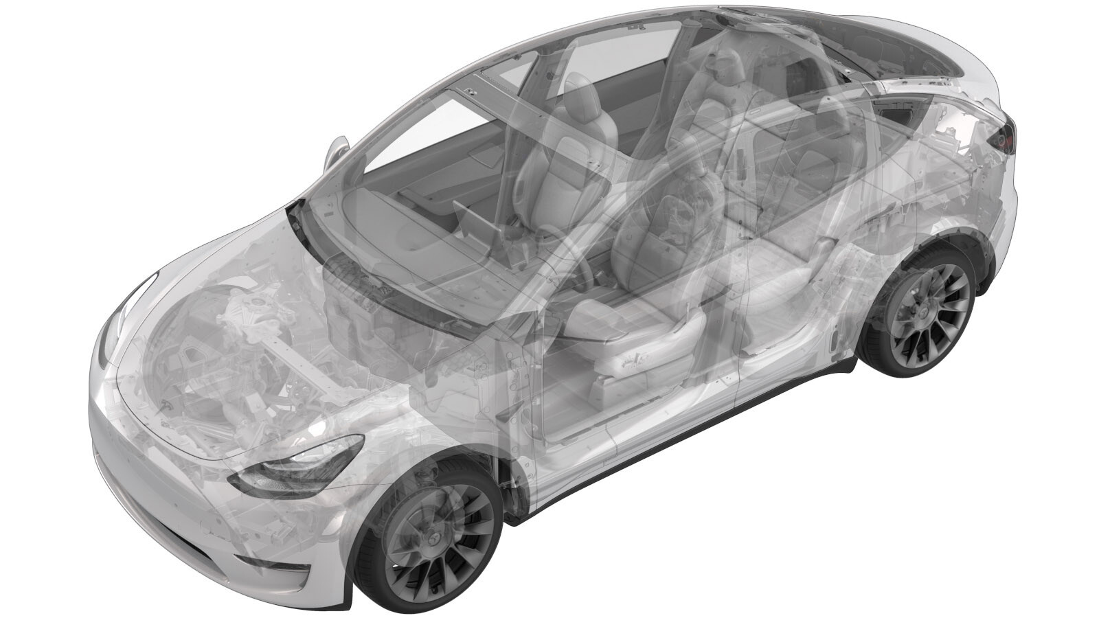
Model Y shown, other models similar
- Disconnect LV power. See 12V/LV Power (Disconnect and Connect).
-
Disconnect the restraint control module connectors (x2).
-
Remove and discard the nuts (x3) that attach the restraint control module to the vehicle.8 Nm (5.9 lbs-ft)TIpUse of the following tool(s) is recommended:
- 10mm socket
-
Lift the restraint control module off the alignment studs, and then slide the module out from under the riser to remove it from the vehicle.
Install
-
Position the restraint control module under the riser, and then align the module onto the alignment studs.
NoteSlide module under riser and align holes with studs
-
Install new nuts (x3) that attach the restraint control module to the vehicle.8 Nm (5.9 lbs-ft)TIpUse of the following tool(s) is recommended:
- 10mm socket
-
Connect the restraint control module connectors (x2).
- Install the RH center console side panel. See Side Panel - Center Console - LH (Remove and Replace).
- Connect LV power. See 12V/LV Power (Disconnect and Connect).
-
Position the HEPA filter assembly into the vehicle, and then install the bolts (x2) that attach the assembly to the vehicle.5 Nm (3.7 lbs-ft)NotePivot the front edge down past the frunk assembly, and then carefully move the rear edge past the brake reservoir and into position.TIpUse of the following tool(s) is recommended:
- 10mm socket
- Install the rear underhood apron. See Underhood Apron - Rear (Remove and Replace).
- Reinstall the vehicle firmware. See Software Reinstall - Touchscreen.
- Enter Service Mode Plus. See Service Mode Plus
-
On the touchscreen, touch
.
-
On the next screen, touch Run, and allow the routine
to complete.
-
On the touchscreen, check the
headlight leveling system.
- If the headlight leveling system is "Ride Height Sensor", exit Service Mode, see Service Mode, and discontinue this procedure.
- If the headlight leveling system is "Virtual Pitch Sensor", exit Service Mode, see Service Mode, and continue to the next step.
- Adjust the headlights: