2020-07-02
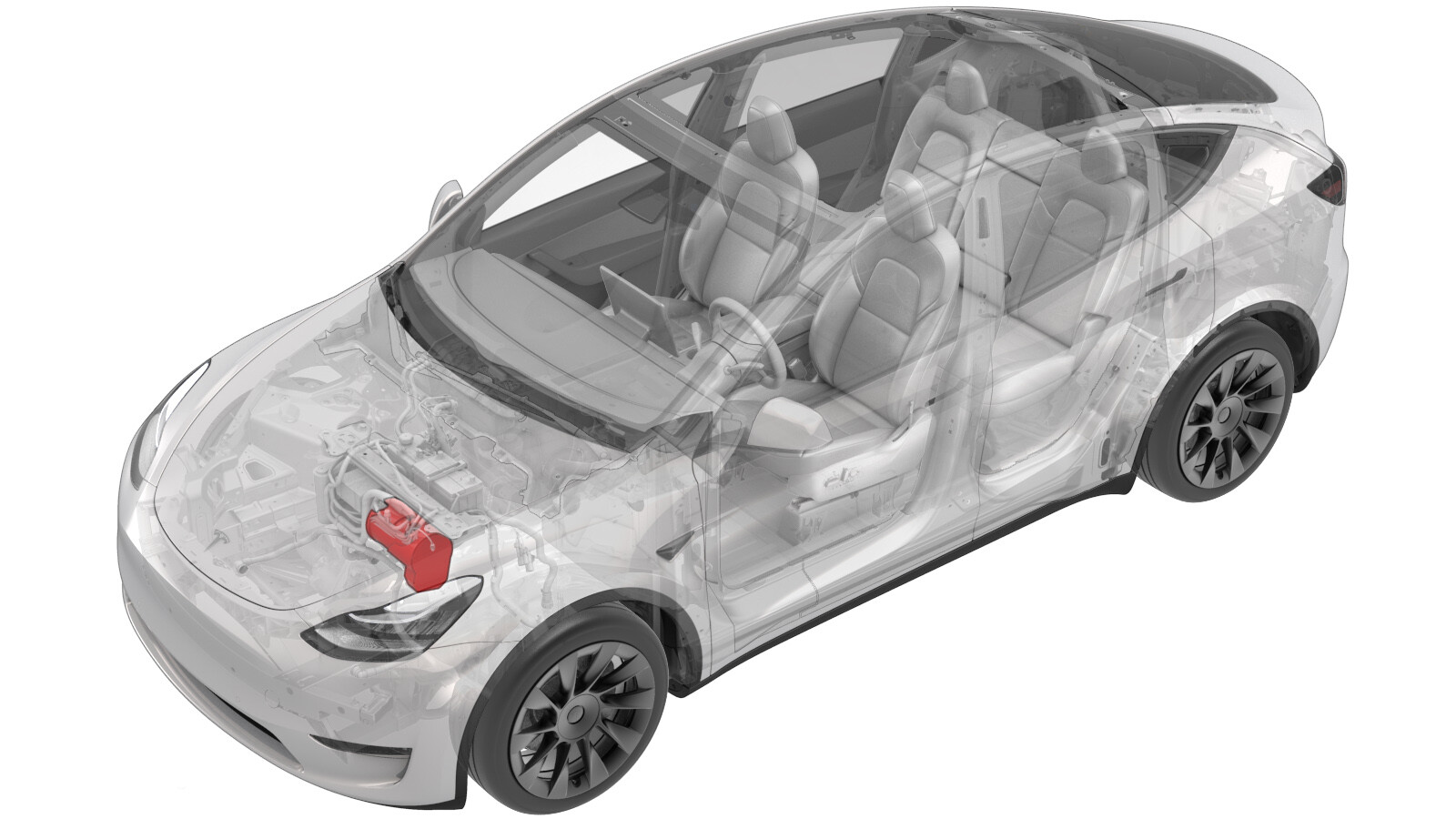
Acoustic Blanket - Compressor (Retrofit)
 Correction code
18203506
0.72
NOTE: Unless otherwise explicitly
stated in the procedure, the above correction code and FRT reflect all of the work
required to perform this procedure, including the linked procedures. Do not stack correction codes unless
explicitly told to do so.
NOTE: See Flat Rate
Times to learn more about FRTs and how they are created.
NOTE: See Personal Protection to make sure wearing proper PPE when
performing the below procedure. NOTE: See Ergonomic Precautions for safe and healthy working
practices.
Correction code
18203506
0.72
NOTE: Unless otherwise explicitly
stated in the procedure, the above correction code and FRT reflect all of the work
required to perform this procedure, including the linked procedures. Do not stack correction codes unless
explicitly told to do so.
NOTE: See Flat Rate
Times to learn more about FRTs and how they are created.
NOTE: See Personal Protection to make sure wearing proper PPE when
performing the below procedure. NOTE: See Ergonomic Precautions for safe and healthy working
practices.
Warning
Only
technicians who have completed all required certification courses are permitted to
perform this procedure. Tesla recommends third party service provider technicians
undergo equivalent training before performing this procedure. For more information on
Tesla Technician requirements, or descriptions of the subject matter for third parties,
see HV Certification Requirements. Proper personal protective equipment (PPE) and insulating HV
gloves with a minimum rating of class 0 (1000V) must
be worn at all times a high voltage cable, busbar, or fitting is handled. Refer to Tech Note TN-15-92-003,
High Voltage Awareness Care Pointsfor additional safety information.
Remove
- Remove the underhood storage unit. See Underhood Storage Unit (Remove and Replace).
- Disconnect 12V power. See 12V/LV Power (Disconnect and Connect).
- Perform the vehicle electrical isolation procedure. See Vehicle HV Disablement Procedure.
- Position a fender protector on the fan shroud and frunk support beam.
- Remove the 12V auxiliary battery. See 12V/LV Battery (Remove and Replace).
-
Remove the rear battery tie down strap from the 12V battery bracket.
NoteThe 12V battery bracket also functions as the A/C compressor bracket.
-
Release the clip that attaches the 12V battery vent tube to the 12V battery
bracket.
-
Release the clips (x4) that attach the
coolant hoses to the 12V battery bracket.
-
Release the connector locking tab, and
then disconnect the low voltage electrical connector from the A/C compressor.
CAUTIONDO NOT push down on the red locking tab. Pull the tab away from the connector until the connector is unlocked, and then continue pulling the main body of the connector to fully disconnect it.
-
Release the clip that attaches the
A/C compressor low voltage harness to the A/C compressor HV harness bracket.
-
Remove the bolt that attaches the HV
harness bracket to the A/C compressor.
TIpUse of the following tool(s) is recommended:
-
Remove the bolt that attaches the
ground strap to the A/C compressor, and then set the ground strap aside.
TIpUse of the following tool(s) is recommended:
-
Release the clip that attaches the
coolant hose to the A/C compressor bracket, near the ground strap attachment
point.
-
Release the clips that attach the A/C
compressor HV harness to the strut tower support brace.
NoteDo not pull on the HV harness
-
Release the connector locking tab, and then disconnect the HVIL connector near the LH
front strut tower.
CAUTIONDO NOT push down on the red locking tab. Pull the tab away from the connector until the connector is unlocked, and then continue pulling the main body of the connector to fully disconnect it.
-
Pull the A/C compressor HV connector
black locking tab away from the A/C compressor.
-
Using a 45-degree pick, simultaneously
push on the central locking tab while pulling on the outer locking tab, and remove the
HV connector from the A/C compressor.
- Move the HV harness bracket forward and up to release the bracket from the A/C compressor, and then carefully set the bracket aside.
-
With assistance, remove the bolts that
attach the A/C compressor assembly to the strut tower brace, and then carefully rest
the A/C compressor assembly on the fender protector.
TIpUse of the following tool(s) is recommended:
-
Remove the bolts that attach the A/C
compressor bracket to the A/C compressor, and then remove the bracket from the
compressor.
TIpUse of the following tool(s) is recommended:
Retrofit
- Clean the outer surfaces of the A/C compressor with IPA wipes.
-
Make 2 cuts on the acoustic blanket as indicated by the red lines so that the blanket
will fit around the A/C pipes.
NoteDo not remove the adhesive backing yet.
-
Without removing the adhesive backing, perform a test fitting of the acoustic blanket
on the A/C compressor, making sure the blanket properly fits around all mounts, pipes,
and electrical connections.
Figure 1. Acoustic blanket at front of A/C compressor Figure 2. Acoustic blanket at rear of A/C compressor - Remove the adhesive backing, and then install the acoustic blanket on the A/C compressor.
-
Position the A/C compressor bracket
on the A/C compressor, and then install the bolts (x3) that attach the bracket to the
compressor.
TIpUse of the following tool(s) is recommended:
- Using a blow gun, clean the bolt holes that are used to attach the A/C compressor bracket to the front strut tower support brace.
-
With an assistant supporting the A/C
compressor assembly under the strut tower brace, hand-start the bolts that attach the
A/C compressor assembly to the brace, and then torque the bolts.
TIpUse of the following tool(s) is recommended:
-
Position the A/C compressor HV
harness bracket on the A/C compressor.
NoteMake sure the HV harness bracket engages with the harness mount on the top of the A/C compressor, as indicated.
-
Fully seat the A/C compressor HV
connector on the A/C compressor, and then engage the locking tab by pushing it toward
the A/C compressor.
NotePerform a push-pull test to verify that the connector is fully attached.
-
Install the clips that attach the A/C compressor HV harness to the strut tower
support brace.
-
Connect the HVIL connector near the LH front strut tower, and then engage the locking
tab.
CAUTIONPush the red locking tab towards the connector to engage the locking mechanism. DO NOT push down or pull up on the red locking tab.
-
Install the clip that attaches the
coolant hose to the A/C compressor bracket, near the ground strap attachment
point.
-
Position the ground strap on the A/C
compressor, and then install the bolt that attaches the ground strap to the A/C
compressor.
TIpUse of the following tool(s) is recommended:
-
Install the bolt that attaches the HV
harness bracket to the A/C compressor.
TIpUse of the following tool(s) is recommended:
-
Install the clip that attaches the
A/C compressor low voltage harness to the A/C compressor HV harness bracket.
-
Connect the low voltage electrical
connector to the A/C compressor, and then engage the locking tab.
CAUTIONPush the red locking tab towards the connector to engage the locking mechanism. DO NOT push down or pull up on the red locking tab.
-
Install the clips (x4) that attach the
coolant hoses to the A/C compressor bracket.
-
Install the rear battery tie down strap on the 12V battery bracket.
-
Install the clip that attaches the 12V battery vent tube to the 12V battery
bracket.
- Install the 12V auxiliary battery. See 12V/LV Battery (Remove and Replace).
- Remove the fender protector from the vehicle.
- Install the underhood storage unit. See Underhood Storage Unit (Remove and Replace).
- Install the 2nd row lower seat cushion. See Seat Cushion - Lower - 2nd Row (Remove and Replace).
- Reconnect 12V power. See 12V/LV Power (Disconnect and Connect).
- Install the rear underhood apron. See Underhood Apron - Rear (Remove and Replace).