Module - Steering Column Control (Remove and Replace)
 Correction code
32011002
0.24
NOTE: Unless otherwise explicitly
stated in the procedure, the above correction code and FRT reflect all of the work
required to perform this procedure, including the linked procedures. Do not stack correction codes unless
explicitly told to do so.
NOTE: See Flat Rate
Times to learn more about FRTs and how they are created. To provide feedback on
FRT values, email ServiceManualFeedback@tesla.com.
NOTE: See Personal Protection to make sure wearing proper PPE when
performing the below procedure. See Ergonomic Precautions for safe and healthy working practices.
- 2024-03-21: Deleted the Toolbox routine per the latest validation.
- 2023-11-30: Replaced Toolbox routine PROC-VCLEFT_X_STEERING-COLUMN-CALIBRATIONvia Toolbox: (link) with PROC_STEERING_COLUMN_CALIBRATIONvia Toolbox: (link)via Service Mode: Chassis ➜ Steering ➜ Calibrate Steering Column.
- 2023-08-28: Updated Toolbox routines to be run after SCCM installation.
Torque Specifications
| Description | Torque Value | Recommended Tools | Reuse/Replace | Notes |
|---|---|---|---|---|
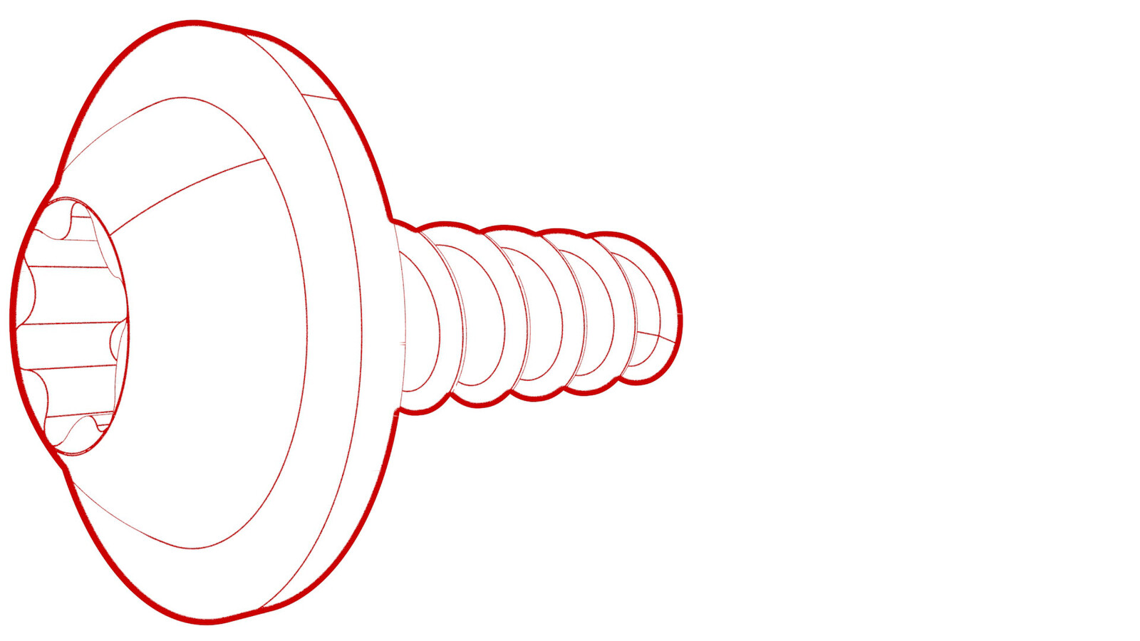
| Upper screws that attach the steering column lower shroud to steering column |
 1.5 Nm (1.1 lbs-ft) |
|
Reuse | |
| Lower screw that attaches steering column lower shroud to steering column |
 1.5 Nm (1.1 lbs-ft) |
|
Reuse | |
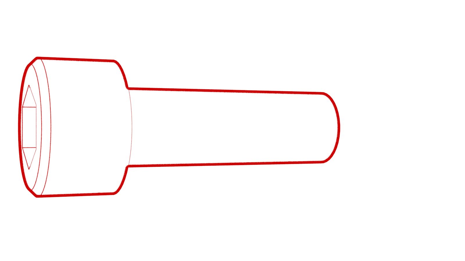
| Bolt that attaches the steering column control module to the steering column |
 9 Nm (6.6 lbs-ft) |
|
Reuse | |
Remove
- Open the LH front door, and fully lower all windows.
- Center the steering wheel, and make sure that the front wheels are pointing straight.
- Remove the rear underhood apron. See Underhood Apron - Rear (Remove and Replace).
- Disconnect 12V/LV power. See 12V/LV Power (Disconnect and Connect).
- Remove the driver airbag. See Airbag - Driver (Remove and Replace).
- Remove the steering wheel. See Steering Wheel (Remove and Install).
-
Release the clips that attach the steering column upper shroud to the lower shroud, and then pull the upper shroud up.
-
Remove the upper screws that attach the steering column lower shroud to the steering column.
TIpUse of the following tool(s) is recommended:
- Torx T20 socket
- ¼ in std ratchet
- 2 in extension
-
Wiha TorqueVario-S 0.8 Nm -
2.0 Nm screwdriver (installation only)
- Torx T20 bit, 70 mm
- Wiha ¼ in bit holder adapter
- Wiha torque setter
-
Remove the lower screw that attaches the steering column lower shroud to the steering column, and then remove the lower shroud from the vehicle.
TIpUse of the following tool(s) is recommended:
- Torx T20 socket
- ¼ in std ratchet
- 2 in extension
-
Wiha TorqueVario-S 0.8 Nm -
2.0 Nm screwdriver (installation only)
- Torx T20 bit, 70 mm
- Wiha ¼ in bit holder adapter
- Wiha torque setter
-
Remove and discard the retaining clip from the steering column control module connector, and then disconnect the electrical harness from the steering column control module connector.
CAUTIONCheck for broken clip pieces on the connector, and remove if present.
- Make sure that the clockspring tape indicator is visible in the inspection window in the upper left of the steering column control module.
-
Remove the bolt that attaches the steering column control module to the steering column.
TIpUse of the following tool(s) is recommended:
- 5 mm hex ball end bit
- ¼ in std ratchet
- ¼ in torque wrench (installation only)
- 2 in extension
-
Remove the steering column control module from the steering column.
NoteIf the steering column control module removed will be re-installed, make sure not to disturb the splined collar in the center of the module.
Install
- Make sure that the clockspring tape indicator is visible in the inspection window in the upper left of the steering column control module.
-
Carefully install the steering column control module onto the steering column, and then install the bolt that attaches the steering column control module to the steering column.
 9 Nm (6.6 lbs-ft)TIpUse of the following tool(s) is recommended:
- 5 mm hex ball end bit
- ¼ in std ratchet
- ¼ in torque wrench (installation only)
- 2 in extension
- Install an orange plastic retaining clip (1028053-00-A) into the electrical harness connector for the steering column control module.
-
Connect the electrical harness to the steering column control module connector.
- Perform a push-pull-push test to make sure that the steering column control module electrical connector is seated properly.
-
Install the lower screw that attaches the steering column lower shroud to the steering column.
 1.5 Nm (1.1 lbs-ft)TIpUse of the following tool(s) is recommended:
- Torx T20 socket
- ¼ in std ratchet
- 2 in extension
-
Wiha TorqueVario-S 0.8 Nm -
2.0 Nm screwdriver (installation only)
- Torx T20 bit, 70 mm
- Wiha ¼ in bit holder adapter
- Wiha torque setter
-
Install the upper screws that attach the steering column lower shroud to the steering column.
 1.5 Nm (1.1 lbs-ft)TIpUse of the following tool(s) is recommended:
- Torx T20 socket
- ¼ in std ratchet
- 2 in extension
-
Wiha TorqueVario-S 0.8 Nm -
2.0 Nm screwdriver (installation only)
- Torx T20 bit, 70 mm
- Wiha ¼ in bit holder adapter
- Wiha torque setter
-
Install the clips that attach the steering column upper shroud to the lower shroud.
- Remove the red locking tab from the new steering column control module by lifting it off.
- Install the steering wheel. See Steering Wheel (Remove and Install).
- Install the driver airbag. See Airbag - Driver (Remove and Replace).
- Connect 12V/LV power. See 12V/LV Power (Disconnect and Connect).
- Install the rear underhood apron. See Underhood Apron - Rear (Remove and Replace).
- Enter Service Mode. See Service Mode.
- Update the vehicle firmware. See Software Update.
- Exit Service Mode. See Service Mode.
- Raise all windows and close the LH front door.