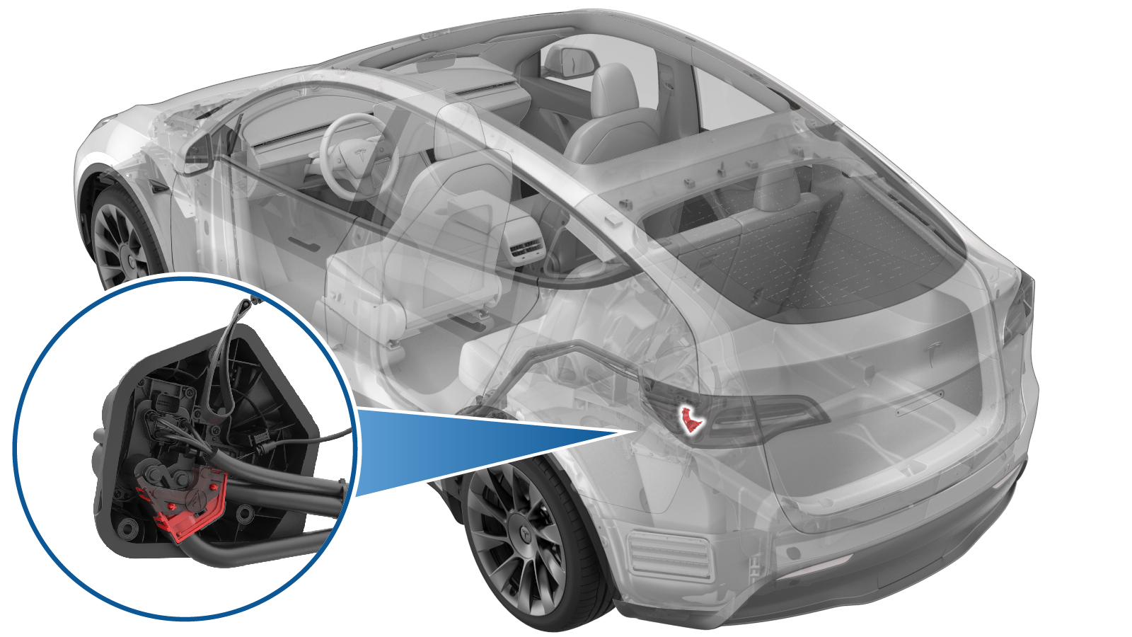
Bracket - Busbar - Charge Port to HV Battery (3-Phase) (Remove and Replace)
 Correction code
44011902
0.66
NOTE: Unless otherwise explicitly
stated in the procedure, the above correction code and FRT reflect all of the work
required to perform this procedure, including the linked procedures. Do not stack correction codes unless
explicitly told to do so.
NOTE: See Flat Rate
Times to learn more about FRTs and how they are created.
NOTE: See Personal Protection to make sure wearing proper PPE when
performing the below procedure. NOTE: See Ergonomic Precautions for safe and healthy working
practices.
Correction code
44011902
0.66
NOTE: Unless otherwise explicitly
stated in the procedure, the above correction code and FRT reflect all of the work
required to perform this procedure, including the linked procedures. Do not stack correction codes unless
explicitly told to do so.
NOTE: See Flat Rate
Times to learn more about FRTs and how they are created.
NOTE: See Personal Protection to make sure wearing proper PPE when
performing the below procedure. NOTE: See Ergonomic Precautions for safe and healthy working
practices.
Remove
- Remove the 3-phase charge port to HV battery busbar safety cap. See Safety Cap - Busbar - Charge Port to HV Battery (3-Phase) (Remove and Replace).
-
Remove the nuts (x2) that attach the charge port busbar leads to the charge
port assembly, and then remove the busbars from the charge port..
TIpUse of the following tool(s) is recommended:
- 10 mm deep socket
-
Use a pick to gently release the tabs (x3) that attach the busbar retainer
bracket to the busbar bracket, and then remove the retainer bracket from the
vehicle.
NoteDo not pry with excessive force, as doing so could damage the brackets.
- Remove the busbar bracket from the charge port busbars.
Install
- Perform a zero adjust of the Hioki resistance meter in preparation to measure resistances later in this procedure. See Resistance Meter (Zero Adjust).
-
Perform a torque check on the busbar studs on the back of the charge
port.
 2 Nm (1.5 lbs-ft)NoteSkip this step if installing a new charge port assembly.TIpUse of the following tool(s) is recommended:
- Torx T10 bit
-
Clean the charge port busbar HV header at the back of the charge port
assembly with an IPA wipe.
TIpUse a plastic trim tool to push the IPA wipe into the crevices of the charge port busbar HV header.
-
Use an IPA wipe to clean all
residue and debris from the charge port busbar leads, and then air dry for 1
minute.
Figure 1. Busbar bracket design may vary - Install the busbar bracket on the charge port busbars.
-
Apply two drops of electrical joint compound on each of the charge port
busbar leads (x2), on the side that makes contact with the charge
port.
NoteMake sure the contact surfaces are completely covered with electrical joint compound.
Figure 2. Busbar bracket design may vary -
Install the busbar retainer bracket on the busbar bracket, making sure to
engage the locking tabs (x3).
NoteDo not pry with excessive force, as doing so could damage the brackets.
-
Install the nuts (x2) that attach the charge port busbar leads to the
charge port assembly.9 Nm (6.6 lbs-ft)NoteIf positioning the busbars requires excessive force, the busbars might be bent. Inspect for damage and replace the busbars if necessary.TIpUse of the following tool(s) is recommended:
- 10 mm deep socket
- Put on HV insulating gloves and leather over gloves.
-
At the charge port, use the Hioki resistance meter to measure the
resistance between the charge port busbar lead and the charge port busbar
stud. Also perform this test on the other lead and stud.
NoteThe acceptable resistance is between 0.050 mΩ (50 μΩ) and 0.270 mΩ (270 μΩ). If the measured resistance is above 270 mΩ (270 μΩ), there is too much resistance in the High Voltage joint. Remove the fastener, clean areas with isopropyl alcohol, install fastener back and test again, as appropriate.NoteIf the resistance is lower than 0.050 mΩ (50 μΩ), reposition the probes and measure again. If after 4 attempts the resistance is consistently lower than 0.050 mΩ (50 μΩ), the test has passed; continue to the next step.
- Remove the HV insulating gloves and leather over gloves.
-
Install the busbar retainer bracket on the busbar bracket, making sure to
engage the locking tabs (x3).
-
Install the safety cap on the busbar brackets, making sure to engage the
two locking tabs.
- Install the LH trunk side trim. See GUID-6E5F19EE-348A-4512-A3A7-D5094875E651.html#GUID-6E5F19EE-348A-4512-A3A7-D5094875E651.
- Install the trunk sill trim. See Trim - Sill - Trunk (Remove and Replace).
- Install the trunk floor trim. See GUID-F67E0EE8-A63B-4E32-85E8-8F77FD67E541.html#GUID-F67E0EE8-A63B-4E32-85E8-8F77FD67E541.
- Install the trunk garnish. See GUID-23140453-C088-49A7-B9ED-7FB4CD0C3D0A.html#GUID-23140453-C088-49A7-B9ED-7FB4CD0C3D0A.
- Install the LH rear sill panel trim. See GUID-F372D367-AB8B-406C-9CCE-00C7545B7802.html.
- Reconnect 12V/LV power. See 12V/LV Power (Disconnect and Connect).