Contactor - Fast Charge - HV Battery (7-Seat) (Remove and Replace)
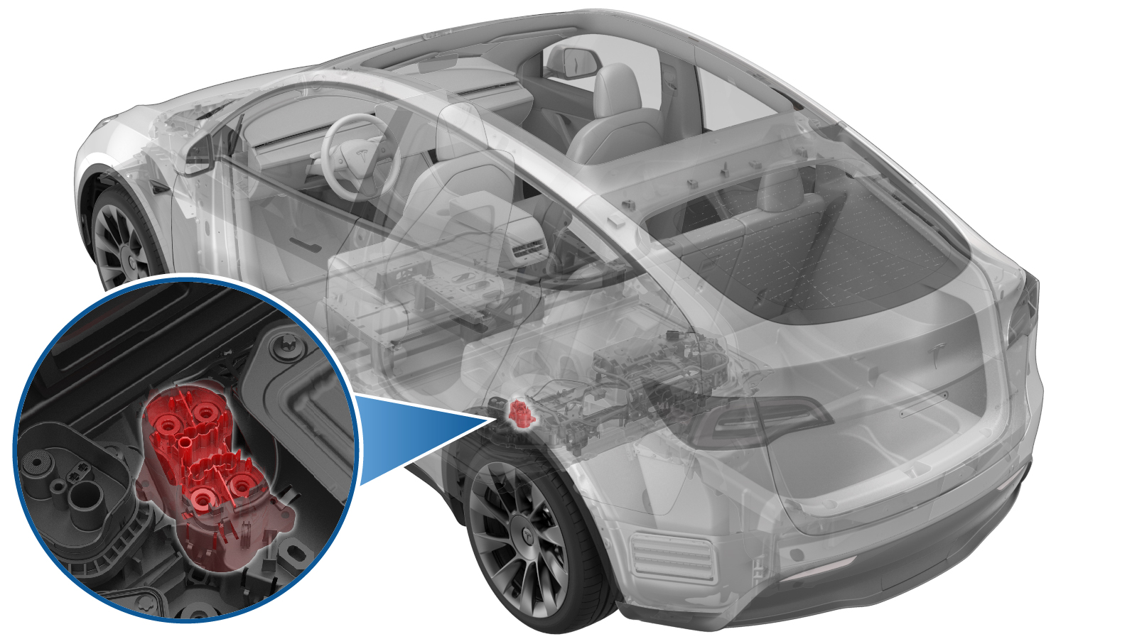 Correction code
16302622
FRT
1.98
NOTE: Unless
otherwise explicitly stated in the procedure, the correction code and its
associated FRT reflect all of the work required to perform this procedure,
including the linked procedures. Do not stack correction
codes unless explicitly told to do so.
NOTE: See Flat Rate Times to
learn more about FRTs and how they are created.
NOTE: See Personal Protection to make
sure you are wearing proper PPE when performing the procedure below.
NOTE: See Ergonomic Precautions for safe and healthy
working practices.
Correction code
16302622
FRT
1.98
NOTE: Unless
otherwise explicitly stated in the procedure, the correction code and its
associated FRT reflect all of the work required to perform this procedure,
including the linked procedures. Do not stack correction
codes unless explicitly told to do so.
NOTE: See Flat Rate Times to
learn more about FRTs and how they are created.
NOTE: See Personal Protection to make
sure you are wearing proper PPE when performing the procedure below.
NOTE: See Ergonomic Precautions for safe and healthy
working practices.
Equipment:
- 1057602-00-A Ratchet, 1/4" Sq Dr, HV Insulated
- 1057603-00-A Ext Bar, Wobble, 1/4" Dr, HV Insulated
- 1057606-00-A Skt, 1/4" Sq Dr, 13mm, HV Insulated
- 1059330-00-B Skt, 1/4in Dr, 5-Lobe Torx Plus External
- 1076927-00-A Resistance meter, microohm, Hioki RM 3548
Only
technicians who have completed all required certification courses are permitted to
perform this procedure. Tesla recommends third party service provider technicians
undergo equivalent training before performing this procedure. For more information on
Tesla Technician requirements, or descriptions of the subject matter for third parties,
see HV Certification Requirements. Proper personal protective equipment (PPE) and insulating HV
gloves with a minimum rating of class 0 (1000V) must
be worn at all times a high voltage cable, busbar, or fitting is handled. Refer to Tech Note TN-15-92-003, High Voltage Awareness
Care Points
for additional safety
information.
Remove
- Remove the ancillary cover. See Cover - Ancillary Bay (7-Seat) (Remove and Install).
- Remove the pyrotechnic battery disconnect. See Pyrotechnic Battery Disconnect (Remove and Replace).
-
Remove the clip that attaches the HV
battery ancillary bay harness to the HV battery fast charge contactor cover.
NoteOn newer packs, this harness clip is located further from the contactor and therefore does not need to be removed for access.
-
Disconnect the electrical harness from the HV battery fast charge contactor connector.
NoteSqueeze the tabs on either side of the harness connector, to release the tabs from the contactor connector.CAUTIONDo not pry the connectors apart, as this action breaks the tabs and connectors, and necessitates harness replacement.
-
Disconnect the HV battery AC inlet harness from the power conversion system connector.
NoteRelease the locking tab by pulling upward. A plastic trim tool may be needed to help lift the connector upward.
-
Release the clips that attach the HV
battery AC inlet harness cover to the power conversion system.
- Remove the HV battery probing guide. See Guide - Probing - HV Battery (Remove and Replace).
- Remove the HV battery DC input assembly. See DC Input Assembly - HV Battery (Busbar Type) (Remove and Replace).
-
Remove and discard the bolts that attach the negative and positive busbars to the DC links and DC input.
-
Remove the clips that attach the HV battery ancillary bay harness to HV battery fast charge contactor cover.
-
Remove the nut and bolts that attach the fast charge contactor to the ancillary bay, and remove the contactor with the harness from the vehicle.
-
Remove the negative AC inlet terminal cover.
Note3 x clips.
-
Release the clips (x8) that attach the
HV battery fast charge contactor cover to the fast charge contactor, and then remove the
cover from the contactor.
CAUTIONThe fast charge contactor cover is a one-time use as the clips are fragile and break easily.
-
Remove and discard the bolts that
attach the busbars to the fast charge contactor, and then remove the busbars from the
contactor.
Install
- Perform a zero adjust of the Hioki resistance meter in preparation to measure resistances later in this procedure. See Resistance Meter (Zero Adjust).
-
Install the positive and negative inlet and DC link busbars to the fast charge
contactor, install new patch bolts (x4) to attach the busbars to the contactor.
Precondition the bolts by torquing to 10 Nm, then back off one half turn, retorque to 10
Nm, and then mark the bolts with a paint pen.
 10 Nm (7.4 lbs-ft) - 180 degrees10 Nm (7.4 lbs-ft)
 - Install the new fastcharge contactor cover to the fastcharge contactor assembly.
-
Install new bolt that secures the positive AC inlet terminal to the positive inlet
fast charge busbar. 4.4 Nm (3.2 lbs-ft)
-
Install new bolt that secures the negative AC inlet terminal to the negative inlet
fast charge busbar.4.4 Nm (3.2 lbs-ft)
-
Use the Hioki resistance meter to measure the resistance at the HV joint between the
positive AC inlet terminal to the positive inlet side fastcharge busbar, and between the
negative AC inlet terminal to negative inlet side fastcharge busbar.
NoteThe maximum acceptable resistance is 0.150 mΩ (150 μΩ). There is too much resistance in the High Voltage joint. Remove the fastener, clean areas with isopropyl alcohol, install fastener back and test again.
-
Position the AC inlet terminal covers
on the negative and positive ring terminals, and then engage the clips that attach the
terminal covers to the negative and positive ring terminals.
-
Position the fast charge assembly to
the ancillary bay for installation.
Note2 guide pins.
-
Install the bolts and nut that attach
the fast charge assembly to the ancillary bay, and then mark the bolts and nut with a
paint pen after they are torqued.5.5 Nm (4.1 lbs-ft)8 Nm (5.9 lbs-ft)
-
Install the clips that attach the HV
battery ancillary bay harness to HV battery fast charge contactor cover.
- Install the HV battery DC input assembly. See DC Input Assembly - HV Battery (Busbar Type) (Remove and Replace).
-
Install new bolts (x4) to attach the
negative and positive busbars to the DC links and DC input, and then mark the bolts with
a paint pen.5 Nm (3.7 lbs-ft) + 60 degrees
-
Use the Hioki resistance meter to measure the resistance at the HV joint of the
fastcharge busbar DC link side.
NoteThe maximum acceptable resistance is 0.025 mΩ (25 μΩ).
-
Use the Hioki resistance meter to measure the resistance at the negative HV joint of
the fastcharge busbar DC link side.
NoteThe maximum acceptable resistance is 0.040 mΩ (40 μΩ).
-
Fasten the clips that attach the
fastcharge contactor HV harness to the power conversion system.
-
Connect the HV battery AC inlet
harness to the power conversion system connector.
-
Connect the electrical harness to the HV battery fast charge contactor
connector.
- Install the HV battery probing guide. See Guide - Probing - HV Battery (Remove and Replace).
-
Install the clip that attaches the HV
battery ancillary bay harness to the HV battery fast charge contactor.
- Measure the voltage across the pyrotechnic battery disconnect mount points, and then install the pyrotechnic battery disconnect. See Pyrotechnic Battery Disconnect (Remove and Replace).
- Install the ancillary cover. See Cover - Ancillary Bay (7-Seat) (Remove and Install).