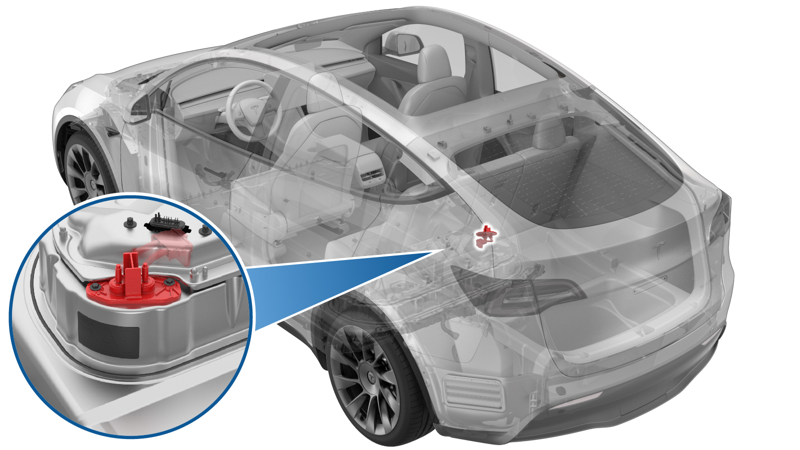
Passthrough - DCDC - 12V (Busbar Type) (Remove and Replace)
 Correction code
16306002
1.38
NOTE: Unless otherwise explicitly
stated in the procedure, the above correction code and FRT reflect all of the work
required to perform this procedure, including the linked procedures. Do not stack correction codes unless
explicitly told to do so.
NOTE: See Flat Rate
Times to learn more about FRTs and how they are created.
NOTE: See Personal Protection to make sure wearing proper PPE when
performing the below procedure. NOTE: See Ergonomic Precautions for safe and healthy working
practices.
Correction code
16306002
1.38
NOTE: Unless otherwise explicitly
stated in the procedure, the above correction code and FRT reflect all of the work
required to perform this procedure, including the linked procedures. Do not stack correction codes unless
explicitly told to do so.
NOTE: See Flat Rate
Times to learn more about FRTs and how they are created.
NOTE: See Personal Protection to make sure wearing proper PPE when
performing the below procedure. NOTE: See Ergonomic Precautions for safe and healthy working
practices.
- 2023-05-22: Added caution for correct positive DC cable connection.
- 2023-08-07: Restructured the procedure.
Equipment:
- 1130480-02-A Slim Test Probes
- 1059330-00-B Skt, 1/4in Dr, 5-Lobe Torx Plus External
- 1076921-00-A Fluke 1587
- 1108272-00-B Cap, Logic Conn, Inv, 3DU
- 1131071-00-A Dummy Disconnect, Pyro, Safety
- 1057602-00-A Ratchet, 1/4" Sq Dr, HV Insulated
| Description | Torque Value | Recommended Tools | Reuse/Replace | Notes |
|---|---|---|---|---|
| Nut that attaches the positive 12V output to the power conversion system cable |
 9 Nm (6.6 lbs-ft) |
|
Replace | |
| Bolts that attach the DCDC passthrough to the ancillary bay |
10 Nm (7.4 lbs-ft) |
|
Reuse |
Remove
- Remove the ancillary bay cover. See Cover - Ancillary Bay (Remove and Install).
- Remove the pyrotechnic battery disconnect. See Pyrotechnic Battery Disconnect (Remove and Replace).
- Install the pyrotechnic disconnect dummy.
-
Disconnect the power conversion system
LV connector.
TIpRelease the locking tab by pulling upward. Use plastic trim tool to help lift the connector upward as needed. Lift the HV controller up from the front.
- Remove the DCDC ground strap from the HV battery. See Busbar - DCDC Ground (Remove and Replace).
-
Release the positive 12V output cover
from the power conversion system cable.
-
Remove and discard the nut that
attaches the positive 12V output to the power conversion system cable, and then move the
cable aside.
Use of the following tool(s) is recommended:
- 13 mm 12-point deep socket
- 6 in extension
- 3 in extension
- Ratchet/torque wrench
- Paint Pen
-
Remove the bolts (x2) that attach the
DCDC passthrough to the ancillary bay.
Use of the following tool(s) is recommended:
- Insulated tools:
- 2 in extension
- Ratchet/torque wrench - 1057602-00-A
- Electrical Protective Gloves
- External Torx E10 5-Lobe - 1059330-00-B
- Ratchet/torque wrench
- Paint Pen
- Insulated tools:
-
Remove the DCDC passthrough from the
ancillary bay.
Install
-
Position the DCDC passthrough to the
ancillary bay for installation, and then install the bolts (x2) that attach the DCDC
passthrough to the ancillary bay.10 Nm (7.4 lbs-ft)Use of the following tool(s) is recommended:TIpMark the bolts after torque.
- Insulated tools:
- 2 in extension
- Ratchet/torque wrench - 1057602-00-A
- Electrical Protective Gloves
- External Torx E10 5-Lobe - 1059330-00-B
- Ratchet/torque wrench
- Paint Pen
- Insulated tools:
-
Install the new nut that attaches the
positive 12V output to the power conversion system cable.9 Nm (6.6 lbs-ft)CAUTIONMake sure the positive output cable is positioned properly and in the right direction against the plastic anti-rotation edge on the DCDC passthrough.Use of the following tool(s) is recommended:CAUTIONMake sure the rubber boot is not pinched between the cable terminal and the passthrough.
- 13 mm 12-point deep socket
- 6 in extension
- 3 in extension
- Ratchet/torque wrench
- Paint Pen
- Install the positive 12V output cover.
- Install the DCDC ground strap to the HV battery. See Busbar - DCDC Ground (Remove and Replace).
-
Connect the power conversion system LV
connector.
TIpPush the connector downward, and then push the locking tab downward to install the connector. Make sure the connector is fully seated. Lift the HV controller up from the front.
- Remove the fuse access insulator and the pyrotechnic disconnect dummy.
- Measure the voltage across the pyrotechnic battery disconnect mount points, and then install the pyrotechnic battery disconnect. See Pyrotechnic Battery Disconnect (Remove and Replace).
- Install the ancillary bay cover. See Cover - Ancillary Bay (Remove and Install).