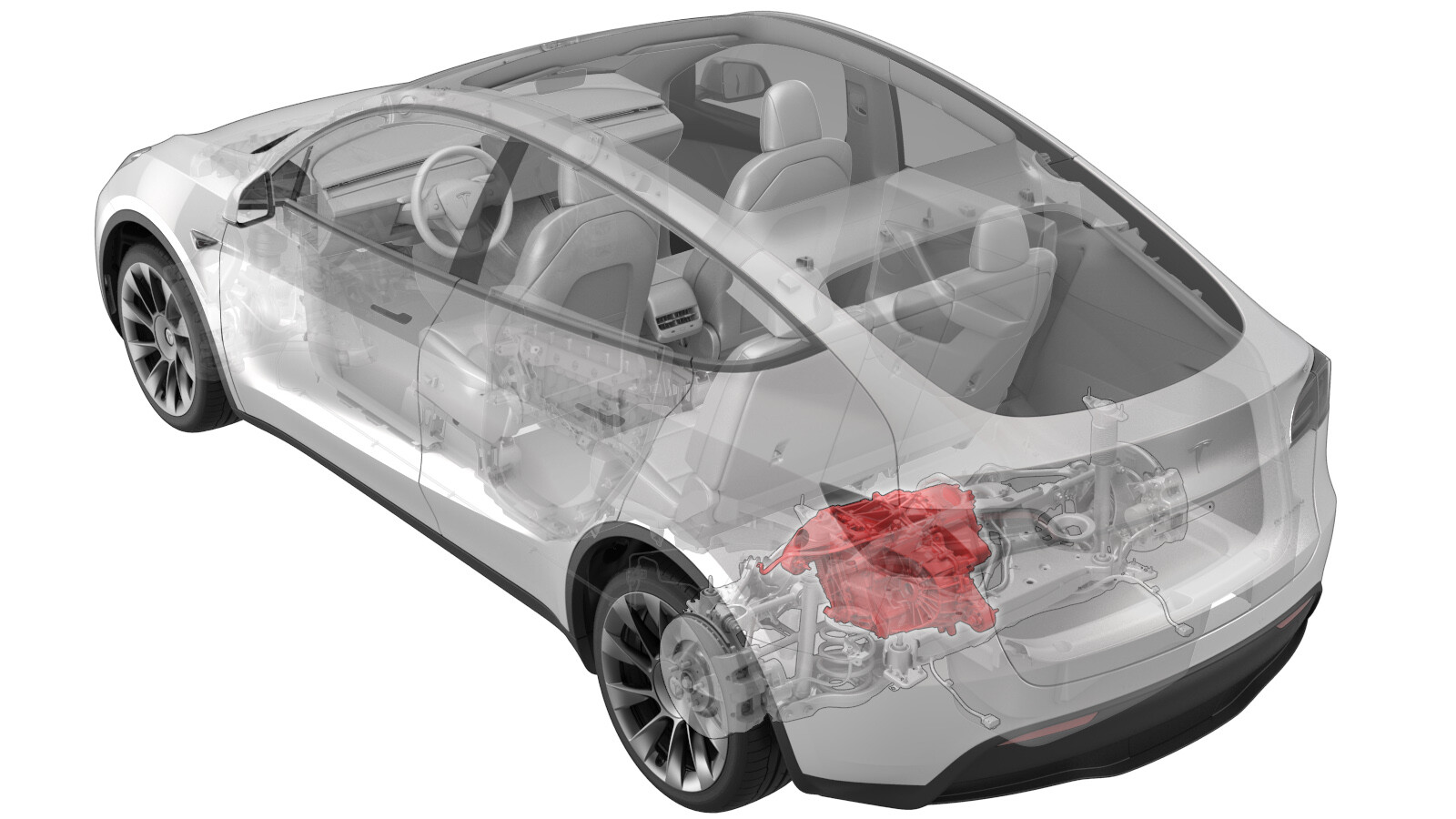
Drive Unit - Rear (4DU) (Remove and Replace)
 Correction code
40011012
4.08
NOTE: Unless otherwise explicitly
stated in the procedure, the above correction code and FRT reflect all of the work
required to perform this procedure, including the linked procedures. Do not stack correction codes unless
explicitly told to do so.
NOTE: See Flat Rate
Times to learn more about FRTs and how they are created.
NOTE: See Personal Protection to make sure wearing proper PPE when
performing the below procedure. NOTE: See Ergonomic Precautions for safe and healthy working
practices.
Correction code
40011012
4.08
NOTE: Unless otherwise explicitly
stated in the procedure, the above correction code and FRT reflect all of the work
required to perform this procedure, including the linked procedures. Do not stack correction codes unless
explicitly told to do so.
NOTE: See Flat Rate
Times to learn more about FRTs and how they are created.
NOTE: See Personal Protection to make sure wearing proper PPE when
performing the below procedure. NOTE: See Ergonomic Precautions for safe and healthy working
practices.
- 2026-07-03: Updated the steps to connect a LV maintainer.
- 2025-11-20: Updated Toolbox routines to ODIN/Service UI routines.
- 2024-01-17: Updated torque figure for the bolt that attaches the ground strap to the RDU from 6 Nm to 10 Nm.
- 2024-01-12: Added a note to install a new motor ID label in hood/trunk for China, Japan and Korea.
- 2023-06-08: Added shear plate small bolts torque figure for Structural Pack type vehicles.
- 2023-03-15: Updated note that drive units are prefilled with KAF 1 gearbox fluid.
Remove
- While performing the courtesy inspection, note any abnormal tire wear that could indicate the need for an alignment.
- Move the vehicle to a 2 post lift. See Raise Vehicle - 2 Post Lift.
-
Chock a front wheel to prevent the
vehicle from rolling in subsequent steps.
- Connect a laptop with Toolbox 3 to the vehicle. See Toolbox (Connect and Disconnect).
- Run PROC_VCFRONT_X_START-THERMAL-FILL-DRAIN-COOLANTvia Toolbox:(link).
- Run PROC_EPB_X_SERVICE-MODE-STARTvia Toolbox:(link).
-
Disconnect the laptop with Toolbox 3
from the vehicle. See Toolbox (Connect and Disconnect).
NoteDo not close this instance of Toolbox 3 as it is needed later on in the procedure.
- Remove the rear underhood apron. See Underhood Apron - Rear (Remove and Replace).
- Remove the HEPA filter assembly. See Assembly - Filter - HEPA (Remove and Replace).
- Remove the HEPA duct. See Duct - HEPA (Remove and Replace).
- Disconnect LV power. See 12V/LV Power (Disconnect and Connect).
- Perform Vehicle HV Disablement Procedure. See Vehicle HV Disablement Procedure.
- Remove the LH and RH rear wheels. See Wheel (Remove and Replace).
- Remove the LH and RH rear suspension covers. See Cover - Rear Suspension - LH (Remove and Replace).
- Remove the mid aero shield panel. See Panel - Aero Shield - Rear (Remove and Replace).
- Remove the rear diffuser. See Diffuser - Rear Fascia (Remove and Replace).
-
Remove the nut that attaches the rear
drive unit ground strap to the body, and then remove the ground strap from the
body.
-
Remove and discard the bolts (x2) that
attach the LH rear brake caliper to the LH rear knuckle, remove the caliper from the
knuckle, and then hang the caliper from an S-hook.
-
Install the Gedore spring compressor
onto the LH rear coil spring, and slightly compress the spring to take the load off of
the suspension.
NoteRefer to the Tooling Profile for additional information.
-
Remove the bolts (x2) that attach the
LH rear strut to the body at the LH top mount.
- Repeat step 18 through step 20 on the RH side of the vehicle.
-
Release
the red locking tab and then disconnect the electrical harness from the rear subframe harness RH
connector.
-
Release the clip that attaches the
rear subframe harness to the body on the RH side.
-
Release
the red locking tab and then disconnect the electrical harness from the rear subframe harness LH
connector.
-
Release the clip that attaches the
rear subframe harness to the body on the LH side.
-
Remove and discard the nut that
attaches the LH rear stabilizer bar end link to the rear stabilizer bar.
NoteUse a 5mm allen wrench to prevent the ball joint stud from turning and damaging the ball joint.
-
Remove LH rear stabilizer bar end link
from the rear stabilizer bar.
NoteMove the stabilizer bar up and down to ease removal of the end link.
-
Remove and discard the nut that
attaches the RH rear stabilizer bar end link to the rear stabilizer bar.
NoteUse a 5mm allen wrench to prevent the ball joint stud from turning and damaging the ball joint.
-
Remove RH rear stabilizer bar end link
from the rear stabilizer bar.
NoteMove the stabilizer bar up and down to ease removal of the end link.
-
Remove and discard the bolts (x4) that
attach the rear stabilizer bar to the rear subframe, and then remove the stabilizer bar
from the subframe.
-
Release the clips (x2) that attach the
coolant hoses to LH shear plate.
-
Release the clips (x4) that attach the
coolant hoses to the rear skid plate.
NoteClip quantity varies with older vehicles.
-
Release the clips (x2) that attach the
coolant hoses to RH shear plate.
- Remove the HV battery rear skid plate. See Skid Plate - HV Battery - Rear (Remove and Replace).
-
Position a coolant drain collector
underneath the LH rear of the HV battery.
-
Release the clip, disconnect the rear
drive unit inverter inlet hose from the HV battery, and then immediately plug both
fittings.
-
Release the clip, disconnect the rear
drive unit inverter inlet hose from the rear drive unit inverter, and then immediately
plug both fittings.
-
Release the clip that attaches the
rear drive unit inverter inlet hose from rear drive unit HV harness.
-
Remove the rear drive unit inverter
inlet hose down and out from between the rear subframe and the HV battery.
-
Position a coolant drain collector
underneath the RH rear of the HV battery.
-
Release the clips (x2) that attach the
RH rear wheel arch liner to the RH rocker panel, and then move the liner aside for
access.
-
Release the clip, disconnect the rear
drive unit coolant outlet hose from the powertrain return hose, and then immediately
plug both fittings.
-
Remove the coolant drain collector
from under the vehicle.
-
Release the locking tab, push the
handle downward, and then disconnect the rear subframe electrical harness from the rear
drive unit inverter logic connector.
CAUTIONOnce disconnected, make sure that coolant does not get into the connectors.
-
Release the clip that attaches the
rear subframe electrical harness to the rear drive unit inverter.
-
Remove the bolt that attaches the rear
drive unit HV harness bracket to the rear drive unit inverter.
-
Slide the locking tab, raise the black
handle, disconnect the rear drive unit HV harness from the rear drive unit inverter HV
header,and then set the HV harness aside.
-
Remove the nut(s) that attach(es) the
rear drive unit HV harness bracket to the HV battery.
-
Slide the red locking tab, raise the
black handle, and then disconnect the rear drive unit HV harness from the HV battery
header.
-
Remove the rear drive unit HV harness
down and out from between the rear subframe and the HV battery.
NoteRotate the harness as it is removed to allow access for the bracket.
-
Position the subframe lifting tool
under, and up against the rear subframe.
-
With the help of an assistant, fully
secure the straps (x3) that attach the rear subframe to the subframe lifting tool.
-
Use a paint pen to trace around the LH
and RH rear subframe mounting bolts, so that the bolts can be realigned later during the
subframe installation.
-
Use a paint pen to apply a witness
mark where the rear subframe contacts the body at the LH and RH rear subframe mounting
bolts, so that the subframe can be realigned to the body later during subframe
installation.
-
Remove the small bolts (x2) that
attach the LH shear plate to the HV battery.
-
Remove the large bolt that attaches
the LH shear plate and rear subframe to the body, and then remove shear
plate.
-
Remove the small bolts (x2) that
attach the RH shear plate to the HV battery.
-
Remove the large bolt that attaches
the RH shear plate and rear subframe to the body, and then remove shear
plate.
-
Remove and discard the LH rear
subframe bolt that attaches the subframe to the body.
-
Remove and discard the RH rear subframe bolt that attaches the subframe to the
body.
-
Carefully lower the rear subframe and
rear drive unit assembly from the vehicle, and move it out from under the vehicle.
CAUTIONDo not damage hoses or harnesses while lowering the subframe.
-
Release the clip that attaches the
rear drive unit ground strap to the rear subframe.
-
Remove the bolt that attaches the rear
drive unit ground strap to the rear drive unit, and then remove the ground strap from
the drive unit.
-
Position a coolant catcher under the
RH side of the subframe and rear drive unit assembly, and position a foldable funnel to
direct coolant drain from the heat exchanger.
-
Release the clip, disconnect the rear
drive unit coolant outlet hose from the rear drive unit heat exchanger, and allow the
heat exchanger and hose to drain.
-
Release clips (x3) that attach the
rear drive unit coolant outlet hose to rear drive unit, and then manuever the hose out
from between the drive unit and rear subframe.
-
Release the clips (x2) that attach the
rear drive unit inverter outlet to heat exchanger hose to the rear drive unit.
-
Cut the rear drive unit inverter NVH
cover at the line indicated so as to access the clip for the rear drive unit inverter to
heat exchanger hose.
NoteOpen the cut in the NVH cover, but be carefull not to remove any of the cover in doing so.
-
Release the clip, disconnect the rear
drive unit inverter to heat exchanger hose from the rear drive unit inverter outlet, and
allow to drain.
-
Release the clip, disconnect the rear
drive unit inverter to heat exchanger hose from the rear drive unit heat exchanger, and
allow to drain.
-
Release the remaining clips (x2) that
attach the rear drive unit inverter outlet to heat exchanger hose to the rear drive
unit, and then manuever the hose out from between the drive unit and rear
subframe.
-
Pull the red tab to release, and then
pull the red tab again to disconnect the rear subframe harness from the oil pump
connector.
-
Pull the red tab to release, pull the
red tab again to disconnect the rear subframe harness from the resolver connector, and
then release the clips (x2) that attach the subframe harness to the rear drive
unit.
-
Remove the bolt that attaches the LH
rear wheel speed sensor to LH rear knuckle, and then remove the sensor from the
knuckle.
-
Release the grommet that attaches the
LH rear wheel speed sensor harness to LH rear knuckle.
-
Remove the nut and bolt that attach
the LH rear upper aft link to the LH rear knuckle.
-
Remove the nut and bolt that attach
the LH rear upper fore link to the LH rear knuckle.
-
Remove the nut and bolt that attach
the LH rear toe link to the LH rear knuckle.
-
Loosen, but do not remove, the nut and
bolt that attach the LH rear lower fore link to the LH rear knuckle.
-
Position the axle remover cable around
the inner joint of the LH rear drive unit halfshaft, and then use the U-bolt to hold the
axle remover cable in position.
-
Hook the axle remover slide hammer
onto the 2 axle remover cable loops, and then use the slide hammer to remove the LH
halfshaft from the rear drive unit.
NoteBe carefull not to damage the halfshaft boots and drive unit seals when separating the halfshaft from the drive unit.
- Repeat step 74 through step 81 on the RH side of the rear subframe assembly.
-
Position the rear subframe assembly
under the gantry.
-
Use the shackles (x3) to attach the
drive unit sling tool to the rear drive unit.
-
Attach the drive unit sling tool to
the gantry.
-
Use the gantry to raise the drive unit
sling tool so that there is slight tension in the cables.
-
Remove the bolt that attaches the rear
drive unit to the LH side of the rear subframe.
-
Remove the bolt that attaches the rear
drive unit to the RH side of the rear subframe.
-
Remove the bolt that attaches the rear
drive unit to the rear of the rear subframe.
-
With the help of an assistant, use the
gantry to raise the rear drive unit sling tool, guide halfshafts away from the rear
drive unit, and separate the rear drive unit up from the rear subframe.
-
Move the rear subframe and subframe
lift out from underneath the rear drive unit, and then lower the rear drive unit onto a
protected surface.
-
Remove the drive unit sling tool from
the rear drive unit.
Install
-
Uncrate the new rear drive unit and
position it underneath the gantry.
NoteThe new drive unit comes prefilled with KAF 1 gearbox fluid.
-
Remove the protective covers and caps
from the new rear drive unit and transfer them to the old rear drive unit.
-
Use the shackles (x3) to attach the
drive unit sling tool to the new rear drive unit.
-
Use the gantry to raise the drive unit
sling tool so that there is slight tension in the cables.
-
Remove the bolts (x3) that attach the
new rear drive unit to the rear drive unit crate.
-
Lift the new rear drive unit out of
the shipping crate and position the rear subframe and subframe lift underneath the drive
unit.
-
With the help of an assistant, use the
gantry to lower the rear drive unit sling tool, guide halfshafts into the rear drive
unit, and lower the rear drive unit into the rear subframe.
-
Lower the rear drive unit sling tool
so as to install and hand tighten the bolt that attaches the rear drive unit to the rear
of the rear subframe.
-
Install and hand tighten the bolt that
attaches the rear drive unit to the RH side of the rear subframe.
-
Install and hand tighten the bolt that
attaches the rear drive unit to the LH side of the rear subframe.
-
Lower the drive unit sling tool to
release tension in the cables, and then remove the sling tool from the rear drive
unit.
-
Tighten the rear drive unit mount
bolts (x3).
 80 Nm (59.0 lbs-ft)
 -
Use the shackles (x3) to attach the
drive unit sling tool to the old rear drive unit.
-
Use the gantry to raise the old rear
drive unit off of the protective surface and position the drive unit over the rear drive
unit crate.
-
With the help of an assistant, use the
gantry to lower the old rear drive unit into the rear drive unit crate.
-
Install and hand tighten the bolts
(x3) that attach the old rear drive unit to the rear drive unit crate.
-
Remove the drive unit sling tool from
the old rear drive unit.
-
Remove the drive unit sling tool from
the gantry.
-
Prepare the rear drive unit crate for
MRB.
-
With the help of an assistant,
slightly rotate the LH halfshaft so as to align the splines of the halfshaft to those in
the rear drive unit, lift up on the LH rear knuckle to help move the halfshaft into the
drive unit, and then apply force to seat the halfshaft in the drive unit.
NoteIf the halfshaft binds, back the halfshaft out, rotate it slightly, and try again.CAUTIONWhen installing the halfshaft(s) into the drive unit:
- Make sure that the opening of the snap ring is facing towards the bottom of the drive unit.
- Do not damage or displace the oil seal.
- Verify that the halfshaft is fully seated:
- Carefully push the halfshaft into the drive unit until there is an audible "click" from the halfshaft stub contacting the pinion shaft.
- There will be a slight pulling sensation on the halfshaft as the halfshaft circlip locks into place.
- Pull on the inner halfshaft cup to confirm that the circlip is locked into place. If the halfshaft detaches from the drive unit then reinstall the halfshaft and then test that it is fully seated.
-
Install the LH rear toe link to the LH
rear knuckle, and then install and hand-tighten the nut and bolt that attach the link to
the knuckle.
-
Install the LH rear upper fore link to
the LH rear knuckle, and then install and hand-tighten the nut and bolt that attach the
link to the knuckle.
-
Install the LH rear upper aft link to
the LH rear knuckle, and then install and hand-tighten the nut and bolt that attach the
link to the knuckle.
-
Fasten the grommet that attaches the
LH rear wheel speed sensor harness to LH rear knuckle.
-
Install the LH rear wheel speed sensor
to LH rear knuckle, and then install the bolt that attaches the sensor to
knuckle.5 Nm (3.7 lbs-ft)
- Repeat step 20 through step 25 on the RH side of the rear subframe assembly.
-
Connect the rear subframe harness to
the resolver connector, push the red tab to secure, and then fasten the clips (x2) that
attach the subframe harness to the rear drive unit.
-
Connect the rear subframe harness to
the oil pump connector, and then push the red tab to secure.
-
Manuever the rear drive unit inverter
outlet to heat exchanger hose in between the rear drive unit and rear subframe, and then
fasten the clips (x2) that attach the hose to the drive unit.
-
Connect the rear drive unit inverter
to heat exchanger hose to the rear drive unit heat exchanger, fasten the clip, and then
perform a Push-Pull-Push check of the fitting.
-
Connect the rear drive unit inverter
to heat exchanger hose to the rear drive unit inverter outlet, fasten the clip, and then
perform a Push-Pull-Push check of the fitting.
-
Fasten the clips (x2) that attach the
rear drive unit inverter outlet to heat exchanger hose to the rear drive unit.
-
Manuever the rear drive unit coolant
outlet hose in between the rear drive unit and rear subframe, and then fasten the clips
(x3) that attach the hose to drive unit.
-
Connect the rear drive unit coolant
outlet hose to the rear drive unit heat exchanger, fasten the clip, and then perform a
Push-Pull-Push check of the fitting.
-
Install the rear drive unit ground
strap to the rear drive unit, and then install the bolt that attaches the ground strap
to the drive unit.
 10 Nm (7.4 lbs-ft)
 -
Fasten the clip that attaches the rear
drive unit ground strap to the rear subframe.
-
Position the rear subframe and rear
drive unit assembly under the vehicle.
-
Carefully raise the subframe and rear
drive unit assembly until they are up against the body.
CAUTIONDo not damage hoses or harnesses while raising the subframe.
-
Install and hand-tighten a new RH rear
subframe bolt to attach the rear subframe to the body.
-
Install and hand-tighten a new LH rear
subframe bolt to attach the rear subframe to the body.
-
Install the RH shear plate to the rear
subframe, and then install a new large bolt to attach the RH shear plate and rear
subframe to the body.
-
Install and hand-tighten the small
bolts (x2) that attach the RH shear plate to the HV battery.
-
Install the LH shear plate to the rear
subframe, and then install a new large bolt to attach the LH shear plate and rear
subframe to the body.
-
Install and hand-tighten the small
bolts (x2) that attach the LH shear plate to the HV battery.
-
Use a pry bar to shimmy the rear
subframe with respect to the body, so that the subframe mounting bolts are centered in
the tracings, and the witness marks align where the subframe contacts the body.
-
Tighten the RH rear subframe bolt that
attaches the rear subframe to the body, and then mark the bolt after
tightenting.165 Nm (121.7 lbs-ft)
-
Tighten the LH rear subframe bolt that
attaches the rear subframe to the body, and then mark the bolt after
tightenting.165 Nm (121.7 lbs-ft)
-
Tighten large bolt that attaches the
LH shear plate and rear subframe to the body, and then mark the bolt after
tightenting.130 Nm (95.9 lbs-ft)
-
Tighten large bolt that attaches the
RH shear plate and rear subframe to the body, and then mark the bolt after
tightenting.130 Nm (95.9 lbs-ft)
-
Tighten the small bolts (x2) that
attach the RH shear plate to the HV battery.
For non-Structural Pack vehicles:35 Nm (25.8 lbs-ft)NoteSome vehicles are equipped with self-tapping bolts in bolt position #8-15 from the factory. If the vehicle is equipped with a bolt with a hexagonal indentation on the bolt head (1637725-00-A), the torque value is 64 Nm.For Structural Pack vehicles:62 Nm (45.7 lbs-ft)
-
Tighten the small bolts (x2) that
attach the LH shear plate to the HV battery.
For non-Structural Pack vehicles:35 Nm (25.8 lbs-ft)NoteSome vehicles are equipped with self-tapping bolts in bolt position #8-15 from the factory. If the vehicle is equipped with a bolt with a hexagonal indentation on the bolt head (1637725-00-A), the torque value is 64 Nm.For Structural Pack vehicles:62 Nm (45.7 lbs-ft)
-
Release the straps (x3) that attach
the rear subframe to the subframe lifting tool.
-
Lower the subframe lifting tool, and
move it out from under the vehicle.
-
Install the rear drive unit HV harness
in and up between the rear subframe and the HV battery.
NoteRotate the harness as it is installed to allow access for the bracket.
-
Verify that the black release lever of
the rear drive unit HV harness connector is in the open position, install the connector
flat and square to the HV battery header, secure the release lever to the closed
position, and then slide the red connector locking tab.
-
Install the nut(s) that attach(es) the
rear drive unit HV harness bracket to the HV battery.10 Nm (7.4 lbs-ft)
-
Verify that the black release lever of
the rear drive unit HV harness connector is in the open position, install the connector
flat and square to the rear drive unit inverter HV header, secure the release lever to
the closed position, and then slide the connector locking tab.
-
Install the bolt that attaches the
rear drive unit HV harness bracket to the rear drive unit inverter.6 Nm (4.4 lbs-ft)
- Inspect the rear subframe electrical harness logic connector and the rear drive unit inverter logic connector for coolant, and use shop air and a clean dry shop towel to remove any coolant from the connectors.
-
Connect the rear subframe electrical
harness to the rear drive unit inverter logic connector, raise the handle upward, and
fasten the locking tab.
-
Fasten the clip that attaches the rear
subframe electrical harness to the rear drive unit inverter.
-
Position a coolant drain collector
underneath the LH rear of the HV battery.
-
Install the rear drive unit inverter
inlet hose in and up between the rear subframe and the HV battery.
-
Fasten the clip that attaches the rear
drive unit inverter inlet hose to rear drive unit HV harness.
-
Remove the plugs from the fittings,
immediately connect the rear drive unit inverter inlet hose to the rear drive unit
inverter, fasten the clip, and then perform a Push-Pull-Push check of the fitting.
-
Remove the plugs from the fittings,
immediately connect the rear drive unit inverter inlet hose to the HV battery, fasten
the clip, and then perform a Push-Pull-Push check of the fitting.
-
Position the coolant drain collector
underneath the RH rear of the HV battery.
-
Remove the plugs from the fittings,
immediately connect the rear drive unit coolant outlet hose to the powertrain return
hose, fasten the clip, and then perform a Push-Pull-Push check of the fitting..
-
Return the RH rear wheel arch liner to
position, and then fasten the clips (x2) that attach the liner to the RH rocker
panel.
-
Remove the coolant drain collector
from under the vehicle.
- Install the HV battery rear skid plate. See Skid Plate - HV Battery - Rear (Remove and Replace).
-
Fasten the clips (x2) that attach the
coolant hoses to RH shear plate.
-
Fasten the clips (x4) that attach the
coolant hoses to the rear skid plate.
NoteClip quantity varies with older vehicles.
-
Fasten the clips (x2) that attach the
coolant hoses to LH shear plate.
-
Install the rear stabilizer bar to the
rear subframe, and then install new bolts (x4) to attach the stabilizer bar to the
subframe.30 Nm (22.1 lbs-ft)
-
Install the LH rear stabilizer bar end
link into the rear stabilizer bar.
NoteMove the stabilizer bar up and down to ease installation of the end link.
-
Install a new nut to attach the LH
rear stabilizer bar end link to the rear stabilizer bar.55 Nm (40.6 lbs-ft)NoteUse a 5mm allen wrench to prevent the ball joint stud from turning and damaging the ball joint.
-
Install the RH rear stabilizer bar end
link into the rear stabilizer bar.
NoteMove the stabilizer bar up and down to ease installation of the end link.
-
Install a new nut to attach the RH
rear stabilizer bar end link to the rear stabilizer bar.55 Nm (40.6 lbs-ft)NoteUse a 5mm allen wrench to prevent the ball joint stud from turning and damaging the ball joint.
-
Fasten the clip that attaches the rear
subframe harness to the body on the LH side.
-
Connect electrical harness to the rear
subframe harness LH connector and then fasten the red locking tab.
-
Fasten the clip that attaches the rear
subframe harness to the body on the RH side.
-
Connect electrical harness to the rear
subframe harness RH connector and then fasten the red locking tab.
-
Install the rear drive unit ground
strap to the body, and then install the nut that attaches the ground strap to the
body.10 Nm (7.4 lbs-ft)
-
Install the LH rear strut to the body
at the LH top mount, and then install the bolts (x2) that attach the strut to the
body.41 Nm (30.2 lbs-ft)
-
Remove the S-Hook, install the LH rear
brake caliper to the LH rear knuckle, and then install new bolts (x2) to attach the
caliper to the knuckle.83 Nm (61.2 lbs-ft)
-
Remove the bolt that attaches the LH
rear brake rotor to the hub.
-
Install the hub jack adapter onto the
LH rear hub and hand-tighten the lug nuts (x5).
-
Use an underhoist stand to support the
hub jack adapter and simulate the LH rear suspension at ride height.
-
Use the rear ride height torque gauge
to verify the LH rear suspension is set to ride height specification.
NoteIt may be necessary to slightly adjust the underhoist stand or Gedore spring compressor tool.
-
The distance between the bottom of the
quarter panel and the center of the rear axle should be 427 mm when the rear suspension
is set to ride height.
NoteIt may be necessary to slightly adjust the underhoist stand or Gedore spring compressor tool.
-
Tighten the bolt and nut that attach
the LH rear upper aft link to the knuckle, and then mark the fasteners with a paint pen
after tightening134 Nm (98.8 lbs-ft)
-
Tighten the bolt and nut that attach
the LH rear upper fore link to the knuckle, and then mark the fasteners with a paint pen
after tightening76 Nm (56.0 lbs-ft)
-
Tighten the bolt and nut that attach
the LH rear toe link to the knuckle, and then mark the fasteners with a paint pen after
tightening76 Nm (56.0 lbs-ft)
-
Tighten the bolt and nut that attach
the LH rear lower fore link to the knuckle, and then mark the fasteners with a paint pen
after tightening76 Nm (56.0 lbs-ft)
-
Remove the underhoist stand from
underneath the LH rear suspension.
-
Remove the lug nuts (x5) that attach
the hub jack adapter, and then remove the hub jack adapter from the
vehicle.
-
Install the bolt that attaches the LH
rear brake rotor to the hub.5 Nm (3.7 lbs-ft)
-
Remove the Gedore spring compressor
from the LH rear coil spring.
NoteRefer to the Tooling Profile for additional information.
- Repeat step 85 through step 99 for the RH side of the vehicle.
- Install the rear diffuser. See Diffuser - Rear Fascia (Remove and Replace).
- Install the mid aero shield panel. See Panel - Aero Shield - Rear (Remove and Replace).
- Install the LH and RH rear suspension covers. See Cover - Rear Suspension - LH (Remove and Replace).
- Install the LH and RH rear wheels. See Wheel (Remove and Replace).
- Perform a cooling system vacuum refill. See Cooling System (Vacuum Refill).
- Connect LV power. See 12V/LV Power (Disconnect and Connect).
- Connect a LV maintainer to the vehicle. See LV Maintainer (Connect and Disconnect).
- Reconnect the laptop with Toolbox 3 to the vehicle. See Toolbox (Connect and Disconnect).
-
Run PROC_VCFRONT_X_STOP-THERMAL-FILL-DRAINvia Service Mode:
- Thermal ➜ Actions ➜ Stop Thermal Fill/Drain
- Thermal ➜ Coolant System ➜ Stop Coolant Fill/Drain
- Thermal ➜ Refrigerant System ➜ Stop Refrigerant Fill/Drain
- Drive Inverter ➜ Front Drive Inverter Replacement ➜ Stop Fluid Fill/Drain
- Drive Inverter ➜ Rear Drive Inverter Replacement ➜ Stop Fluid Fill/Drain
- Drive Inverter ➜ Rear Left Drive Inverter Replacement ➜ Stop Fluid Fill/Drain
- Drive Inverter ➜ Rear Right Drive Inverter Replacement ➜ Stop Fluid Fill/Drain
- Drive Unit ➜ Front Drive Unit Replacement ➜ Stop Coolant Fill/Drain
- Drive Unit ➜ Rear Drive Unit Replacement ➜ Stop Coolant Fill/Drain
- Run PROC_PMR_X_WRITE-DRIVE-TYPEvia Service Mode Plus:Drive Unit ➜ Rear Drive Unit Replacement ➜ Write Drive Typevia Toolbox:(link)
-
Run PROC_EPB_X_SERVICE-MODEvia Service Mode:
- Chassis ➜ Brakes ➜ EPB Service Mode
- Chassis ➜ Brakes ➜ EPB Service Mode
-
Run UPDATE_CAN-REDEPLOYvia Service Mode Plus:
- Drive Inverter Replacement ➜ Drive Inverter DIRE1L Replacement ➜ CAN Redeploy
- Drive Inverter Replacement ➜ Drive Inverter DIRE1R Replacement ➜ CAN Redeploy
- Drive Inverter Replacement ➜ Drive Inverter DIRE2 Replacement ➜ CAN Redeploy
- Drive Inverter ➜ Front Drive Inverter Replacement ➜ CAN Redeploy
- Drive Inverter ➜ Rear Drive Inverter Replacement ➜ CAN Redeploy
- Drive Inverter ➜ Rear Left Drive Inverter Replacement ➜ CAN Redeploy
- Drive Inverter ➜ Rear Right Drive Inverter Replacement ➜ CAN Redeploy
- Drive Unit ➜ Front Drive Unit Replacement ➜ CAN Redeploy
- Drive Unit ➜ Rear Drive Unit Replacement ➜ CAN Redeploy
- Thermal ➜ HVAC ➜ CAN Redeploy
- chassis ➜ DPB Post Replacement ➜ CAN Redeploy
- chassis ➜ ESP Post Replacement ➜ CAN Redeploy
- chassis ➜ IDB Post Replacement ➜ CAN Redeploy
- chassis ➜ RCU Post Replacement ➜ CAN Redeploy
- chassis ➜ ESP Replacement Panel ➜ CAN Redeploy
- chassis ➜ IBST Replacement Panel ➜ CAN Redeploy
- Disconnect the LV maintainer. See LV Maintainer (Connect and Disconnect).
-
Run PROC_DI_X_PAIR-IMMOBILIZER-AND-VEHICLE-ODOMETERvia Service Mode Plus:
- Drive Inverter ➜ Rear Drive Inverter Replacement ➜ Immobilizer/ODO Pairing
- Drive Unit ➜ Rear Drive Unit Replacement ➜ Pair Immobilizer and Vehicle Odometer
-
Run TEST_VCFRONT_X_THERMAL-COOLANT-AIR-PURGEvia Service Mode:
- Thermal ➜ Actions ➜ Coolant Purge Stop or Coolant Purge Start
- Thermal ➜ Coolant System ➜ Coolant Purge Start
- Drive Inverter ➜ Front Drive Inverter Replacement ➜ Coolant Air Purge
- Drive Inverter ➜ Rear Drive Inverter Replacement ➜ Coolant Air Purge
- Drive Inverter ➜ Rear Left Drive Inverter Replacement ➜ Coolant Air Purge
- Drive Inverter ➜ Rear Right Drive Inverter Replacement ➜ Coolant Air Purge
- Drive Unit ➜ Front Drive Unit Replacement ➜ Coolant Air Purge
- Drive Unit ➜ Rear Drive Unit Replacement ➜ Coolant Air Purge
-
Add coolant to the reservoir as
necessary, and install the reservoir cap.
-
Run TEST-SELF_VCFRONT_X_THERMAL-PERFORMANCEvia Service Mode:Thermal ➜ Actions ➜ Test Thermal Performancevia Service Mode Plus:
- Drive Inverter ➜ Front Drive Inverter Replacement ➜ Thermal System Test
- Drive Inverter ➜ Rear Drive Inverter Replacement ➜ Thermal System Test
- Drive Inverter ➜ Rear Left Drive Inverter Replacement ➜ Thermal System Test
- Drive Inverter ➜ Rear Right Drive Inverter Replacement ➜ Thermal System Test
- Drive Unit ➜ Front Drive Unit Replacement ➜ Thermal System Test
- Drive Unit ➜ Rear Drive Unit Replacement ➜ Thermal System Test
- Disconnect the laptop with Toolbox 3 from the vehicle. See Toolbox (Connect and Disconnect).
-
Remove any wheel chocks.
- Install the HEPA duct. See Duct - HEPA (Remove and Replace).
- Install the HEPA filter assembly. See Assembly - Filter - HEPA (Remove and Replace).
- Install the rear underhood apron. See Underhood Apron - Rear (Remove and Replace).
- Remove the vehicle from the 2 post lift. See Raise Vehicle - 2 Post Lift.
- For China, Japan and Korea only: Carefully remove the old motor label from the hood, and install a new motor label to match the new motor information.
- Refer to the Alignment Requirement tables to determine whether an EPAS alignment check (EC) or four wheel alignment check (AC) is necessary. If performed, add the alignment check/adjust correction code as a separate activity to the SV. See Alignment Requirement - Suspension.