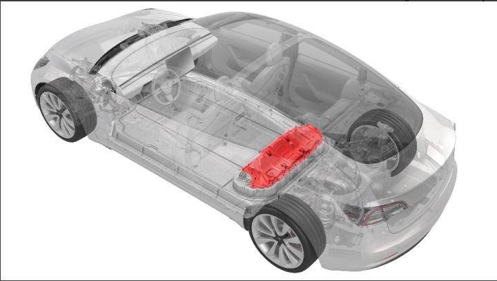
Cover - Ancillary Bay (Structural Pack) (3-Phase) (Remove and Replace)
 Correction code
16101052
1.56
NOTE: Unless otherwise explicitly
stated in the procedure, the above correction code and FRT reflect all of the work
required to perform this procedure, including the linked procedures. Do not stack correction codes unless
explicitly told to do so.
NOTE: See Flat Rate
Times to learn more about FRTs and how they are created.
NOTE: See Personal Protection to make sure wearing proper PPE when
performing the below procedure. NOTE: See Ergonomic Precautions for safe and healthy working
practices.
Correction code
16101052
1.56
NOTE: Unless otherwise explicitly
stated in the procedure, the above correction code and FRT reflect all of the work
required to perform this procedure, including the linked procedures. Do not stack correction codes unless
explicitly told to do so.
NOTE: See Flat Rate
Times to learn more about FRTs and how they are created.
NOTE: See Personal Protection to make sure wearing proper PPE when
performing the below procedure. NOTE: See Ergonomic Precautions for safe and healthy working
practices.
- 2024-07-26: Added information on installing a recycling warning label with CE marking and manufacturer information, if this was present on the ancillary bay cover being replaced.
- 2023-11-08: Added/updated HV insulating glove steps.
- 2023-08-22: Updated images.
- 1108781-BB-F: LABEL - RECYCLING WARNING - EU
Only
technicians who have completed all required certification courses are permitted to
perform this procedure. Tesla recommends third party service provider technicians
undergo equivalent training before performing this procedure. For more information on
Tesla Technician requirements, or descriptions of the subject matter for third parties,
see HV Certification Requirements. Proper personal protective equipment (PPE) and insulating HV
gloves with a minimum rating of class 0 (1000V) must
be worn at all times a high voltage cable, busbar, or fitting is handled. Refer to Tech Note TN-15-92-003, High Voltage Awareness
Care Points
for additional safety
information.
Torque Specifications
| Description | Torque Value | Recommended Tools | Reuse/Replace | Notes |
|---|---|---|---|---|
| Bolts (EPL10 or EPR10) that attach the ancillary bay cover to the HV battery |
 5 Nm (3.7 lbs-ft) |
|
Reuse Replace |
Note Torque these fasteners in the sequence
specified in the installation step. Note These bolts are attached to the ancillary
bay cover. |
| Bolts (EPL10 or EPR10) that attach the charge port header to the ancillary bay cover |
10 Nm (7.4 lbs-ft) |
|
Reuse | |
| Bolts (EPL10) that attach the 3-phase header to the ancillary bay |
6 Nm (4.4 lbs-ft) |
|
Reuse | |
| Bolts (E10 or EPL14) that attach the ancillary bay cover to the HV controller |
10 Nm (7.4 lbs-ft) |
|
||
| Bolts (T20) that attach the PCS LVDC header to the ancillary bay cover |
2.5 Nm (1.8 lbs-ft) |
|
Remove
- Open all the doors and lower the windows.
- Remove the HEPA filter assembly See Assembly - Filter - HEPA (Remove and Replace).
- Move the front seats forward.
- Remove the 2nd row lower seat cushion. See Seat Cushion - Lower - 2nd Row (Remove and Replace).
- Remove the LH and RH lower c-pillar trims. See Trim - C-Pillar - Lower - LH (Remove and Replace).
- Remove the RH 2nd row seat back. See Seat Back - 2nd Row - RH (Remove and Replace).
- Remove the LH 2nd row seat back. See Seat Back - 2nd Row - LH (Remove and Replace).
- Disconnect LV power. See 12V/LV Power (Disconnect and Connect).
- Perform Vehicle HV Disablement Procedure. See Vehicle HV Disablement Procedure (Structural Pack).
- Lower vehicle until tires are touching the ground.
-
Disconnect the HVC logic
connector, and then install the logic connector cap.
-
Disconnect the LV power
connector from the HV battery.
-
Release the red locking tab,
rotate the black lever upwards, and then disconnect the 3-Phase cable
connector from the ancillary bay HV header.
-
Release the clip that
attaches the LH body harness to the rear body and move aside.
Note1x clip.
-
Remove the bolt that closes
the charge port busbar access door at the ancillary bay HV header, and then open
the access door.
TIpUse of the following tool(s) is recommended:
- 10 mm deep socket
-
Remove the bolts (x2) that
attach the charge port busbars to the HV header.
TIpUse of the following tool(s) is recommended:
- 10 mm deep socket
-
Lift busbar kit connector to
remove it from the HV header.
NoteUse an inflatable air bag to suspend the busbar away from the HV header during removal and installation.
-
Remove the NVH insulation
from the ancillary bay cover.
-
Remove the bolts (x3) that
attach the ancillary bay cover to the high voltage controller.
-
Release the bolts (x3) that
attach the PCS Low Voltage DC header to the ancillary bay cover.
-
Release the bolts (x2) that attach the 3-phase header to the
ancillary bay.
-
Release the bolts that attach
the charge port header to the ancillary bay cover, and then remove the
doubler.
NoteTake note of small tabs on shielding.
-
Put on HV insulating gloves
and leather over gloves.
WarningContinue to wear the gloves until instructed to remove them.
-
Remove the perimeter bolts
(x22) that attach the ancillary bay cover to the HV battery.
-
Remove the ancillary bay cover
from the HV battery.
NoteRecommend assistance.
Install
-
For Europe only: Check the ancillary bay cover that is being replaced for the
presence of a recycling warning label that includes a CE marking and manufacturer
information.
- If the recycling warning label with CE marking and manufacturer information is not present on the ancillary bay cover being replaced, continue to the next step.
- If the recycling warning label with CE marking and manufacturer information is
present on the ancillary bay cover being replaced:
- Note the area where the recycling warning label is affixed on the ancillary bay cover being replaced.
- Clean the corresponding area on the new ancillary bay cover with an IPA wipe and allow 1 minute dry time.
- Install a new recycling label with CE marking and Manufacturing Information (part number 1108781-BB-F) on the new ancillary bay cover.
- Inspect the inner edge of the vehicle single-piece rear casting for metal flashing. If flashing is present, put on cut-resistant gloves.
-
Inspect the ancillary bay cover seal
for damage.
NoteIf damage is present, replace the ancillary bay cover seal.
-
Install the ancillary bay cover
onto the HV battery.
NoteRecommend assistance. Guide LH side of cover into position clearing HV header. Maneuver cover past body casting and into position with charge port components.
-
Install the perimeter bolts
(x22) that attach the ancillary bay cover to the HV battery in the order as
shown (torque 5 Nm).
-
Install the doubler, and then
instal the bolts (x2) that attach the charge port header to the ancillary bay
cover (torque 10 Nm).
-
Install the bolts (x2) that attach the 3-phase header to the ancillary bay
(torque 6 Nm).
-
Install the bolts (x3) that
attach the PCS Low Voltage DC header to the ancillary bay cover (torque 2.5
Nm).
-
Install the bolts (x3) that
attach the ancillary bay cover to the high voltage controller (torque 10
Nm).
-
Install the NVH insulation
onto the ancillary bay cover.
-
Connect the LV power
connector to the HV battery.
-
Connect the HVC logic
connector.
-
Install the 3-Phase cable
connector to the ancillary bay HV header.
-
Use IPA wipes to clean the
busbar HV connector contact surface of any residual Penetrox.
-
Use IPA wipes to clean the HV
connector contact surface of residual Penetrox.
-
Apply Penetrox onto the HV
connector joints.
NoteApply 2 drops of Penetrox A-13 about 5 mm in diameter to either side of the hole on both leads. Spread evenly to verify the contact surface is fully covered.
-
Position the busbar kit
connector and lower it onto the HV header.
-
Install the bolts (x2) that attach the charge port busbars to the HV
header (torque 9 Nm).
TIpUse of the following tool(s) is recommended:
- 10 mm deep socket
-
Put on HV insulating gloves
and leather over gloves.
NoteMake sure to wear Electrical Protective Gloves any time Hioki tester is used.
-
Perform the Hioki resistance
test at each HV joint from the HV busbar lead to the bolt head.
Note2x HV joints, The acceptable resistance is between 0.050 mΩ (50 μΩ) and 0.195 mΩ (195 μΩ).If the resistance is greater than 0.195 mΩ (195 μΩ), there is too much resistance in the High Voltage joint. Remove the fastener, clean areas with isopropyl alcohol, install fastener back and test again. If the resistance is lower than 0.050 mΩ (50 μΩ), reposition the probes and measure again. If the resistance is repeatedly between 0.00 mΩ and 0.050 mΩ (50 μΩ), hioki test passed, proceed to next step.
-
Install the bolt that closes the charge port busbar access door at the
ancillary bay HV header (torque 9 Nm).
TIpUse of the following tool(s) is recommended:
- 10 mm deep socket
- Remove HV insulating gloves.
-
Install the clip that
attaches the LH body harness onto the rear body.
- Raise the vehicle to a comfortable working height.
-
Connect the RDU HV harness
connector to the HV battery.
- Install the mid aero shield panel. See Panel - Aero Shield - Rear (Remove and Replace).
- Fully lower the vehicle.
- Connect LV power. See 12V/LV Power (Disconnect and Connect).
- Install the HEPA filter assembly. See Assembly - Filter - HEPA (Remove and Replace).
- Install the rear underhood apron. See Underhood Apron - Rear (Remove and Replace).
- Install the RH 2nd row seat back. See Seat Back - 2nd Row - RH (Remove and Replace).
- Install the RH lower C-pillar trim. See Trim - C-Pillar - Lower - LH (Remove and Replace).
- Install the LH 2nd row seat back. See Seat Back - 2nd Row - LH (Remove and Replace).
- Install the LH lower C-pillar trim. See Trim - C-Pillar - Lower - LH (Remove and Replace).
- Install the 2nd row lower seat cushion. See Seat Cushion - Lower - 2nd Row (Remove and Replace).
- Move the front seats to their original positions.