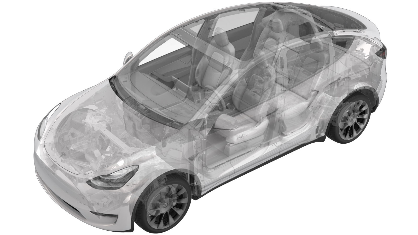
Halfshaft - Rear Drive Unit - LH (Remove and Replace)
 Correction code
40302002
1.02
NOTE: Unless otherwise explicitly
stated in the procedure, the above correction code and FRT reflect all of the work
required to perform this procedure, including the linked procedures. Do not stack correction codes unless
explicitly told to do so.
NOTE: See Flat Rate
Times to learn more about FRTs and how they are created.
NOTE: See Personal Protection to make sure wearing proper PPE when
performing the below procedure. NOTE: See Ergonomic Precautions for safe and healthy working
practices.
Correction code
40302002
1.02
NOTE: Unless otherwise explicitly
stated in the procedure, the above correction code and FRT reflect all of the work
required to perform this procedure, including the linked procedures. Do not stack correction codes unless
explicitly told to do so.
NOTE: See Flat Rate
Times to learn more about FRTs and how they are created.
NOTE: See Personal Protection to make sure wearing proper PPE when
performing the below procedure. NOTE: See Ergonomic Precautions for safe and healthy working
practices.
- 2025-04-04: Added step to refer to the suspension alignment tables to define whether an alignment check is required and, if so, what type of alignment check is required.
- 2023-10-25: Updated torque figure for rear upper fore link to knuckle from 76 Nm to 84 Nm.
- 2023-08-28: Updated EPB Service Mode reference.
- 2023-06-29: Added the whole procedure video as an overview for supplemental purposes only.
Equipment:
- 1134520-00-A Kit, EPB Release, Handheld
- 1129348-00-A XP-10 Power Supply, XP-10
- 1498673-00-A KIT, CABLE AXLE REMOVER, MS/MX/M3
- 1096075-00-A Hub Puller Tool, Hydraulic
Remove
- Raise the vehicle on a 2 post lift. See Raise Vehicle - 2 Post Lift.
- Enable the EPB Service Mode. See Parking Brake - Caliper - Rear - LH (Release)
- Loosen the LH rear wheel lug nuts, but do not remove the wheel at this time. See Wheel Assembly (Remove and Install).
-
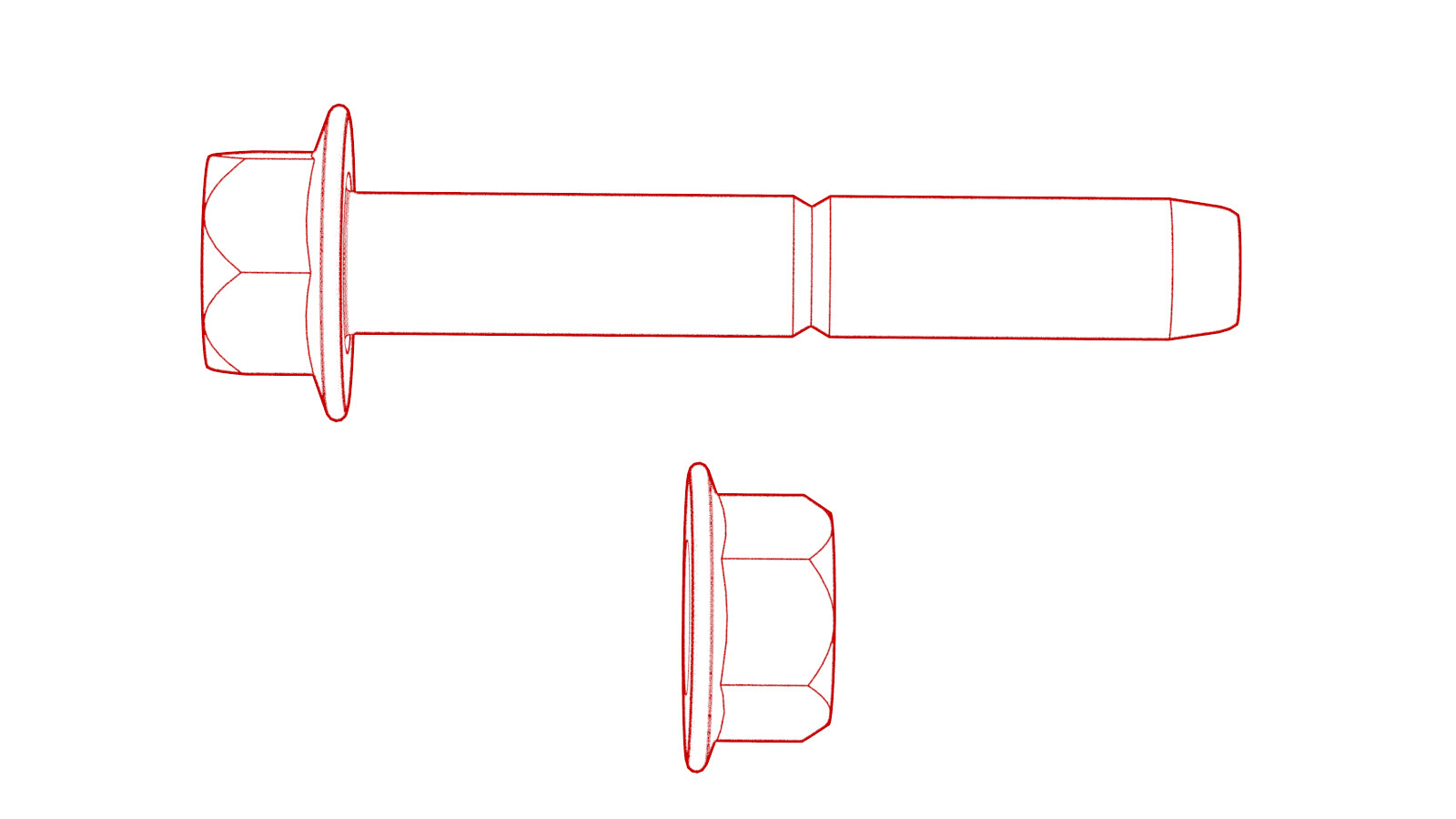
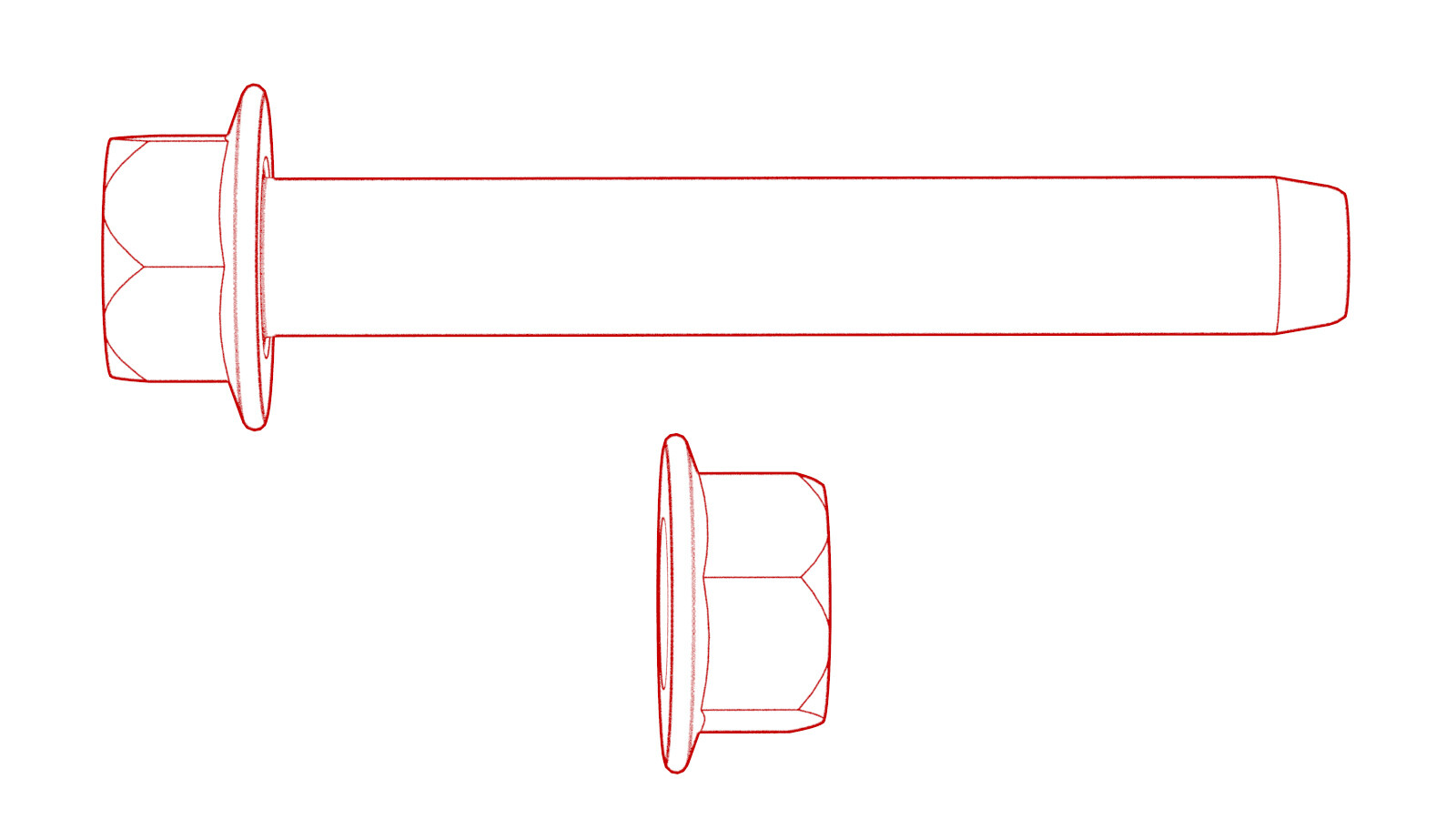
Loosen the LH rear axle nut, but do not remove the nut at this time.
TIpUse of the following tool(s) is recommended:
- 32mm deep impact socket
- Remove the mid aero shield panel. See Panel - Aero Shield - Rear (Remove and Replace).
- Remove the LH rear suspension cover. See Cover - Rear Suspension - LH (Remove and Replace).
- Remove the LH rear wheel.
-
Remove and discard the bolts that attach the LH rear caliper bracket to the
knuckle.
TIpUse of the following tool(s) is recommended:
- E18 socket
- Remove the LH rear brake caliper from the LH rear suspension, and then allow it to hang from the body using an S-hook.
-
Remove and discard the bolt that attaches the rear LH ABS wheel speed
sensor to the knuckle, and then remove the sensor from the knuckle.
TIpUse of the following tool(s) is recommended:
- 10mm socket
- 4 in extension
-
Release the clip and remove the grommet that attach the rear LH ABS wheel
speed sensor cable to the rear LH knuckle and subframe bracket.
-
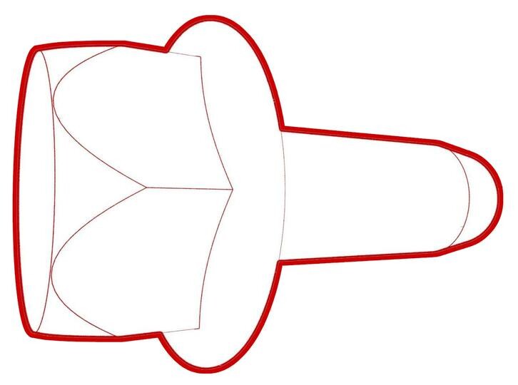
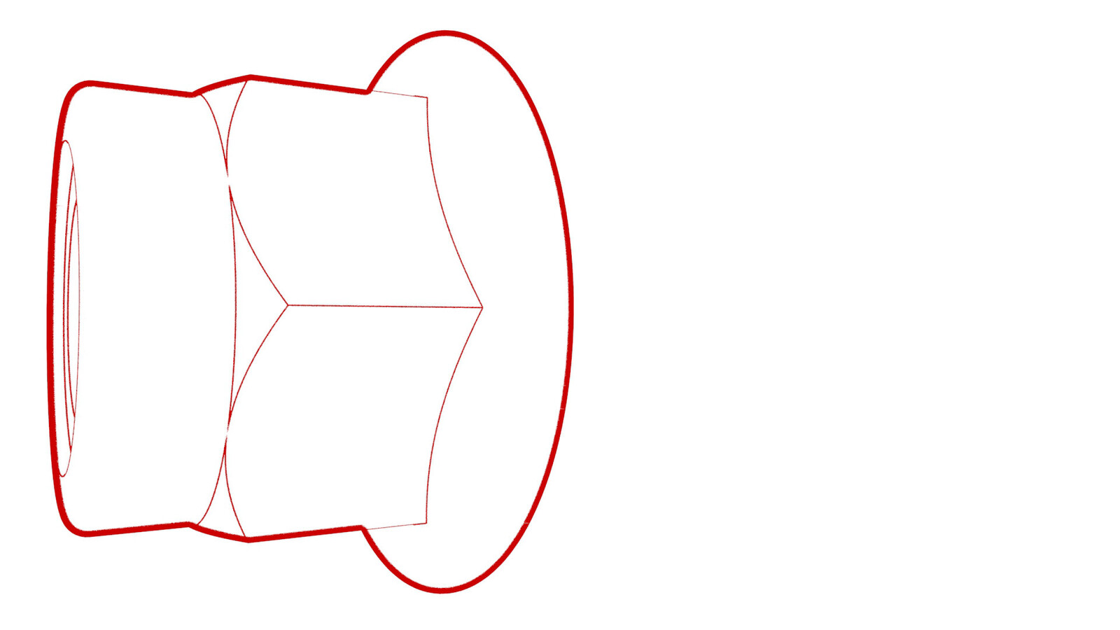
Remove and discard the nut, and remove the washer that attach the LH
halfshaft to the hub assembly.
TIpUse of the following tool(s) is recommended:
- 32mm deep impact socket
-
Remove the bolt that
attaches the brake rotor to the hub.
NoteUse of the following tool(s) is recommended:
- 10 mm socket
- 2 in extension
- Install the hub puller onto the LH rear rotor, and then install and hand-tighten the puller washers (x5) and the lug nuts (x5) onto the rotor studs.
-
Use the hub puller to free the halfshaft from the hub splines.
NoteThe halfshaft is removed at a later step.
- Remove the lug nuts (x5) and the puller washers (x5) from the LH rear rotor studs, and then remove the hub puller from the rotor.
-
Install the bolt that attaches the brake rotor to the hub.
 5 Nm (3.7 lbs-ft)TIpUse of the following tool(s) is recommended:
- 10mm socket
- 2 in extension
- Flex head ratchet / torque wrench
-
Install a spring compressor onto the LH rear coil spring.
TIpUse of the following tool(s) is recommended:
- Gedore Spring Compressor
-
Position a support stand underneath the LH rear suspension.
-
Remove the bolts that attach the LH rear damper at the top mount.
TIpUse of the following tool(s) is recommended:
- 15mm socket
- 3 in extension
-
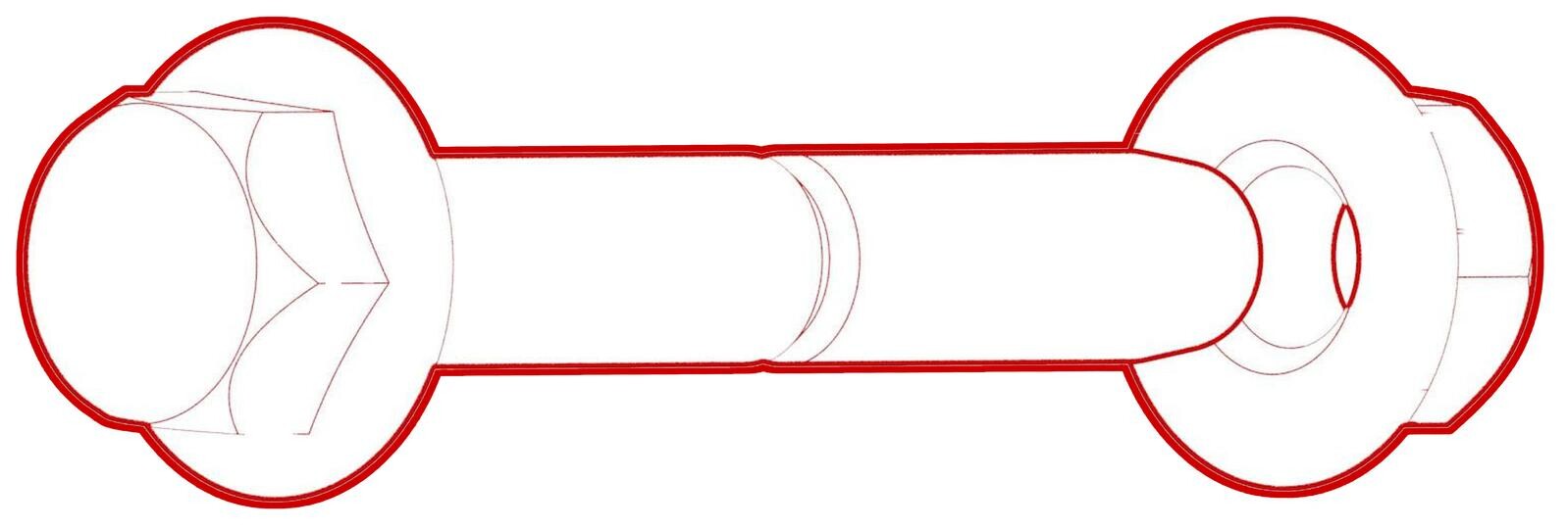
Remove and discard the nut that attaches the rear stabilizer bar link to
the rear stabilizer bar, and then remove the stabilizer bar from the LH end
link.
TIpUse of the following tool(s) is recommended:
- 15mm socket
- 15 mm flex head combination wrench
- 5 mm hex socket
NoteBreak the nut loose, and then counter-hold the ball joint with a 5 mm hex wrench. -
Remove the bolt and nut that attach the LH upper aft link to the
knuckle.
TIpUse of the following tool(s) is recommended:
- 21mm socket
- 6 in extension
- 21 mm ratcheting combination wrench
-
Remove the bolt and nut that attach the LH upper fore link to the
knuckle.
TIpUse of the following tool(s) is recommended:
- 18mm socket
- 3 in extension
- 18 mm ratcheting combination wrench
-
Remove the bolt and nut that attach the LH toe link to the knuckle.
TIpUse of the following tool(s) is recommended:
- 18mm socket
- 18 mm ratcheting combination wrench
- Lower the support stand to gain access for halfshaft removal.
-
With assistance, separate
the halfshaft from the hub assembly, and then move the halfshaft
aside.
WarningTo reduce the risk of personal injury, wear cut resistant gloves and proper personal protective equipment (PPE) as required when removing the halfshaft. Keep hands clear from other components to prevent injury when the halfshaft releases from the Drive Unit.
-
Position the axle remover cable around the inner joint of the LH rear drive
unit halfshaft, and then use a cable tie to hold the axle remover cable in
position.
Figure 1. Axle removed from drive unit for demonstration purposes -
Hook the axle remover slide hammer on the 2 axle remover cable loops, and
then use the slide hammer to remove the halfshaft from the drive unit.
Install
-
Apply approximately 1 gram of Molykote M-77 Lubricant
Paste only to the hub mating face on the outboard side of the LH
rear drive unit halfshaft.
CAUTIONDo not apply any lubricant to the halfshaft splines. If lubricant is mistakenly applied, wipe the splines clean with a shop towel.
-
Install the halfshaft into
the rear drive unit.
CAUTIONWhen installing the halfshaft to the drive unit:
- Take care not to damage or displace the oil seals.
- Make sure that the opening of the snap rings are facing towards the bottom of the drive unit.
- Carefully push the halfshaft into the drive unit until there is an audible "click" from the halfshaft stub contacting the pinion shaft.
- There will be a slight pulling sensation on the halfshaft as the halfshaft circlip locks into place.
- Pull on the inner halfshaft cup to confirm that the circlip is locked into place. If the halfshaft detaches from the drive unit then reinstall the halfshaft and then test that it is fully seated.
- Set the LH halfshaft temporarily on the lower aft link.
- Swing out the upper section of the knuckle and mate the halfshaft to the hub.
- Align the splines of the LH rear halfshaft with those of the LH rear hub, and then install the halfshaft into the hub.
-
Hand-tighten a new nut and washer that
attach the LH rear halfshaft to the hub assembly.
NoteDo not use power tools to tighten the nut as it might strip the threads.NoteThe axle nut is torqued in a later step.
-
With an assistant, install and hand-tighten the bolt and nut that attach
the LH toe link to the knuckle.
-
With an assistant, install and hand-tighten the bolt and nut that attach
the LH upper fore link to the knuckle.
-
With an assistant, install and hand-tighten the bolt and nut that attach
the LH upper aft link to the knuckle.
-
Install a new nut to attach the rear stabilizer bar link to the rear
stabilizer bar, and then mark the nut with a paint pen.
 55 Nm (40.6 lbs-ft)TIpUse of the following tool(s) is recommended:
- 15mm socket
- 15 mm flex head combination wrench
- 5 mm hex socket
NoteCounter-hold the ball joint with a 5 mm hex wrench. -
Install the bolts that attach the LH rear damper at the top mount.
 41 Nm (30.2 lbs-ft)TIpUse of the following tool(s) is recommended:
- 15mm socket
- 3 in extension
-
Remove the support stand from underneath the LH rear suspension.
-
Remove the bolt that
attaches the brake rotor to the hub.
NoteUse of the following tool(s) is recommended:
- 10 mm socket
- 2 in extension
-
Install the hub jack adapter
onto the LH rear hub and hand-tighten the lug nuts.
-
Use an underhoist stand to
support the hub jack adapter.
-
Raise the support stand to simulate vehicle at ride height.
NoteMake sure that the support stand does not block access to adjust the spring compressor or suspension bolts.NoteUse the rear ride height torque gauge to verify that the rear suspension is set to ride height specifications and adjust the support stand or spring compressor tool, if necessary.
-
Measure the distance between the bottom of the quarter panel to the center
of the rear axle to make sure that the rear suspension is set to ride
height: The distance should measure 427 mm.
-
Tighten the bolt and nut that attach the LH toe link to the knuckle, and
then mark the bolt and nut with a paint pen.
 76 Nm (56.0 lbs-ft)TIpUse of the following tool(s) is recommended:
- 18mm socket
- 18 mm ratcheting combination wrench
-
Tighten the bolt and nut that attach
the LH rear upper fore link to the knuckle, and then mark the bolt and nut with a paint
pen.
 84 Nm (61.9 lbs-ft)TIpUse of the following tool(s) is recommended:
- 18mm socket
- 3 in extension
- 18 mm ratcheting combination wrench
-
Tighten the bolt and nut
that attach the LH rear lower fore link to the knuckle, and then mark the
bolt and nut with a paint pen.76 Nm (56.0 lbs-ft)TIpUse of the following tool(s) is recommended:
- 18 mm socket
-
Tighten the bolt and nut that attach
the LH upper aft link to the knuckle, and then mark the bolt and nut with a paint
pen.
 134 Nm (98.8 lbs-ft)TIpUse of the following tool(s) is recommended:
- 18mm socket
- 3 in extension
- 18 mm ratcheting combination wrench
- Remove the support stand from underneath the LH rear suspension.
- Remove the hub jack adapter.
-
Install the bolt that
attaches the brake rotor to the hub.5 Nm (3.7 lbs-ft)
- Remove the spring compressor from the LH coil spring.
-
Install the grommet and fasten the clip that attach the rear LH ABS wheel
speed sensor cable to the rear LH knuckle and subframe bracket.
-
Install the rear LH ABS wheel speed
sensor to the LH rear knuckle, and then install a new bolt to secure the sensor to the
knuckle.
 5 Nm (3.7 lbs-ft)TIpUse of the following tool(s) is recommended:
- 10mm socket
- 4 in extension
-
Install the new bolts that attach the
LH rear caliper bracket to the knuckle.
 83 Nm (61.2 lbs-ft)TIpUse of the following tool(s) is recommended:
- E18 socket
- Install the LH rear wheel, and then hand-tighten the lug nuts that attach the LH rear wheel to the hub.
- Install the mid aero shield panel. See Panel - Aero Shield - Rear (Remove and Replace).
- Install the LH rear suspension cover. See Cover - Rear Suspension - LH (Remove and Replace).
- Lower the vehicle and put the vehicle into Park.
-
Tighten the wheel lug
nuts.175 Nm (129.1 lbs-ft)
-
Tighten the LH rear axle
nut.300 Nm (221.2 lbs-ft)TIpUse of the following tool(s) is recommended:
- 32mm deep impact socket
- Install the LH rear wheel center cap or the hub cap.
- Remove the vehicle from the lift.
- Refer to the Alignment Requirement tables to determine whether an EPAS alignment check (EC) or four wheel alignment check (AC) is necessary. If performed, add the alignment check/adjust correction code as a separate activity to the SV. See Alignment Requirement - Suspension.