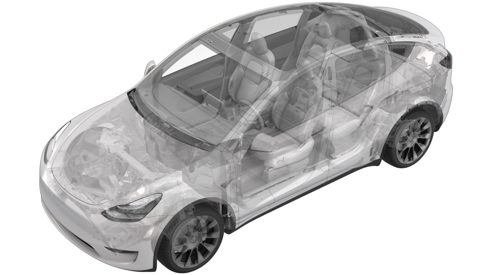
HV Battery (AWD) (7-Seat) (Remove and Install)
 Correction code
16010231
4.08
NOTE: Unless otherwise explicitly
stated in the procedure, the above correction code and FRT reflect all of the work
required to perform this procedure, including the linked procedures. Do not stack correction codes unless
explicitly told to do so.
NOTE: See Flat Rate
Times to learn more about FRTs and how they are created.
NOTE: See Personal Protection to make sure wearing proper PPE when
performing the below procedure. NOTE: See Ergonomic Precautions for safe and healthy working
practices.
Correction code
16010231
4.08
NOTE: Unless otherwise explicitly
stated in the procedure, the above correction code and FRT reflect all of the work
required to perform this procedure, including the linked procedures. Do not stack correction codes unless
explicitly told to do so.
NOTE: See Flat Rate
Times to learn more about FRTs and how they are created.
NOTE: See Personal Protection to make sure wearing proper PPE when
performing the below procedure. NOTE: See Ergonomic Precautions for safe and healthy working
practices.
- 2026-06-10: Updated the torque of the nut that attaches the DCDC ground strap to the HV battery from 15 Nm to 9 Nm.
- 2025-10-10: Changed procedure sequence for cleaning the HV busbar and HV header connector contact surfaces.
- 2025-10-06: Removed redundant step to install LH footwell cover.
- 2024-11-07: Added 3-phase harness disconnect/connect steps.
- 2024-06-13: Updated lift pad adapter PNs.
- 2023-11-21: Added new lift pad instructions.
- 2023-08-29: Updated EPB Service Mode reference.
Only
technicians who have completed all required certification courses are permitted to
perform this procedure. Tesla recommends third party service provider technicians
undergo equivalent training before performing this procedure. For more information on
Tesla Technician requirements, or descriptions of the subject matter for third parties,
see HV Certification Requirements. Proper personal protective equipment (PPE) and insulating HV
gloves with a minimum rating of class 0 (1000V) must
be worn at all times a high voltage cable, busbar, or fitting is handled. Refer to Tech Note TN-15-92-003, High Voltage Awareness
Care Points
for additional safety
information.
Remove
- Remove the LH and RH rocker panel carriers. See Carrier - Rocker Panel - LH (Structural Pack) (Remove and Replace).
-
Remove butyl patches covering LH rocker access holes
Note2x butyl patches, Clean excess butyl from area
-
Install lift pad adapters.
- For EMEA only, install Adapter, Lift Pad, Model Y (1614078-00-A)
- For other regions, install Universal Lift Pad Adapters (1936724-00-A)
WarningDO NOT use any other lift pad adapters.NoteOutside of EMEA, Universal Lift Pad Adapters (1936724-00-A) replace Adapter, Lift Pad, Model Y (1614078-00-A). Discard any other versions of lift pad adapters.NoteIn EMEA, the Universal Lift Pad Adapters are not yet available. Make sure to use the rubber Model Y lift pads on Model Y and the Model 3 lift pads on Model 3.Instructions for Universal Lift Pad Adapters:
- Open all doors and lower the windows.
-
Chock LH rear wheel.
- Enable the EPB Service Mode. See Parking Brake - Caliper - Rear - LH (Release)
-
Perform the following
routine using Service Mode or Toolbox (see 0005 - Service Modes):
PROC_VCFRONT_X_START-THERMAL-FILL-DRAINvia Service Mode:
- Thermal ➜ Actions ➜ Start Thermal Fill/Drain
- Thermal ➜ Coolant System ➜ Start Coolant Fill/Drain
- Thermal ➜ Refrigerant System ➜ Start Refrigerant Fill/Drain
- Drive Inverter ➜ Front Drive Inverter Replacement ➜ Start Fluid Fill/Drain
- Drive Inverter ➜ Rear Drive Inverter Replacement ➜ Start Fluid Fill/Drain
- Drive Unit ➜ Front Drive Unit Replacement ➜ Start Coolant Fill/Drain
- Drive Unit ➜ Rear Drive Unit Replacement ➜ Start Coolant Fill/Drain
NoteThis will ensure the octovalve is in the Series position, Coolant pumps will also be disabled. Once run is selected, the routine is in progress despite the prompt with loading circle. The routine will time out after several hours and will return valves to the parallel position if unattended. Select 'X' at top right of window to close once routine is complete. - Remove the rear underhood apron. See Underhood Apron - Rear (Remove and Replace).
- Remove the LH lower A-pillar trim. See Trim - A-Pillar - Lower - LH (Remove and Replace).
-
Move the LH front seat backward.
NoteEnsure profile is saved to allow seat position to be restored
-
Remove screw and clips securing LH footwell cover
Note2x push clips, 1x screw, T20, 2.5 Nm
-
Remove connectors from LH footwell cover and remove from vehicle
Note3x tabs, 1x Ethernet connector, 1x puddle light connector
-
Remove LH front floor mat
-
Remove LH console side panel carpet
Note11x clips, 2x guide pins, Use trim tool starting at top edge to release upper clips, then pull bottom to release remaining clips, Use caution and pull panel straight away from console, if panel is peeled off it could be damaged
-
Remove clip securing LH front cabin carpet to body
Note1x clip
-
Fold LH front cabin carpet rearward
NoteManeuver carpet below brake pedal and accelerator pedal, Newer Vins may be equipped with additional foam installed below carpet
-
Remove foam plugs to access LH front inner HV battery bolts
Note2x plugs, Push pick through foam and turn roughly 45 degrees to grab onto foam insert and pull straight out, Newer vins may be equipped with 1x foam plug
-
Remove both LH front inner HV battery bolts
Note2x bolts, EP20, 136 Nm
-
Raise LH front seat cushion to maximum height
NoteThis will allow access to HV battery bolts at LH front foot well and below LH front seat
-
Remove RH IP end cap
Note3x clips
-
Remove RH mid A-pillar assembly
Note1x clip, 1x tab, Release the upper clip then pull mid A-pillar upward to remove
-
Remove clip securing RH lower A-pillar trim
Note1x push clip
-
Remove RH lower A-pillar trim
Note6x clips, 2 guide tabs, Pull rear of lower A-pillar upward to release clip then pull rearward to release trim panel
- Move the RH front seat back.
-
Remove clips securing RH footwell assembly
Note4x push clips, Clip count may vary depending on region
-
Remove RH footwell assembly
Note2x connectors
-
Remove RH front floor mat
-
Remove RH console side panel carpet
Note12x clips, 2x locating pins, Use trim tool starting at top edge to release upper clips, Pull bottom to release remaining clips, Use caution and pull panel straight away from console, if panel is peeled off it could be damaged
-
Remove clip securing RH front cabin carpet to body
Note1x clip
-
Fold RH front cabin carpet rearward
NoteNewer Vins may be equipped with additional foam installed below carpet
-
Remove foam plugs to access RH front inner HV battery bolts
Note2x plugs, Push pick through foam and turn roughly 45 degrees to grab onto foam insert and pull straight out, Newer vins may be equipped with 1x foam plug
-
Remove both RH front inner HV battery bolts
Note2x bolts, EP20, 136 Nm
-
Raise RH front seat cushion to maximum height
NoteThis will allow access to HV battery bolts at RH front foot well and below RH front seat
-
Remove 2nd row floor mat from vehicle
-
Separate carpet perforation below RH front seat to access RH middle inner HV battery bolt
NoteLocated below rear of RH front seat
-
Remove RH middle inner HV battery bolt
Note1x bolt, 16mm, 66 Nm
-
Separate carpet perforation below LH front seat to access LH middle inner HV battery bolt
NoteLocated below rear of LH front seat
-
Remove LH middle inner HV battery bolt
Note1x bolt, 16mm, 66 Nm
-
Partially remove LH rear door seal
-
Remove LH 7s lower C-pillar trim
Note8x clips, Rear edge secures onto trunk side trim, Release front clips then rear clips
-
Fold down 2nd row 60 seatback assembly
NotePress button, fold forwards
-
Move 60 seat forward using towel bar
NoteWith one hand on towel bar pull up and slide the seat forward with your other hand
-
Remove 60 seat rear outboard track fastener
Note1x patch bolt, 11mm, 37 Nm, Discard after removal
-
Remove 60 seat rear inboard track fasteners
Note2x patch bolts, 11mm, 37 Nm, Discard after removal
-
Move 60 seat fully rearward using towel bar
NoteWith one hand on towel bar pull up and slide the seat forward with your other hand
-
Remove 60 seat outboard track cover
Note1x clip, Slide covers forward to release from 60 seat tracks
-
Remove center track cover from 2nd row seats
Note2x clips, Slide covers forward to release from 2nd row seat tracks
-
Release cabin carpet from 60 seat
NotePull cabin carpet towards front of vehicle
-
Remove 60 seat front inboard track fasteners
Note1x bolts, 11mm, 37 Nm, Discard after removal
-
Remove 2nd row 60 seat frame front outboard track fasteners
Note1x bolts, 11mm, 37 Nm, Discard after removal
-
Disconnect 2nd row 60 seat connector
Note1x connector
-
Remove 2nd row 60 seat assembly from vehicle
NoteRecommend assistance
-
Partially remove RH rear door seal
NotePillar and sill trim have tabs seated underneath seal
-
Remove RH 7s lower C-pillar trim
Note8x clips, Rear edge secures onto trunk side trim, Release front clips then rear clips
-
Remove 40 seat outboard track cover
Note1x clip, Slide cover forward to release from 40 seat track
-
Release cabin carpet from 40 seat
NotePull cabin carpet towards front of vehicle
-
Remove bolts securing 40 seat podium to vehicle
Note2x patch bolts, 11mm, 37 Nm, Discard bolts after removal
-
Fold 2nd row 40 seat down
-
Move 40 seat forward using towel bar
NoteWith one hand on towel bar pull up and slide the seat forward with your other hand
-
Remove bolts securing 40 seat inner and outer tracks to vehicle
Note2x patch bolts, 11mm, 37 Nm, Discard bolts after removal
-
Move 40 seat fully rearward using towel bar
NoteWith one hand on towel bar pull up and slide the seat rearward with your other hand
-
Disconnect 2nd row 40 seat connector
Note1x connector
-
Remove 40 seat from vehicle
NoteRecommend assistance, Do not support 40 seat by cushion pan, Support 40 seat by podium
-
Position object beneath rear cabin carpet to raise and allow access to rear inner HV battery bolts
NoteUse shop towel or similar
-
Remove RH rear inner HV battery bolt
Note1x bolt, 16mm, 66 Nm, Located below RH rear main carpet
-
Remove LH rear inner HV battery bolt
Note1x bolt, 16mm, 66 Nm, Located below LH rear main carpet
- Power off the vehicle using the touchscreen.
-
Disconnect the 12V negative battery cable and First Responder Loop.
-
Make a slit in 3rd row carpet around LH seat belt
NoteCut a thin straight line on 3rd row carpet from seat belt opening to edge of carpet
-
Make a slit in 3rd row carpet around RH seat belt
NoteCut a thin straight line on 3rd row carpet from seat belt opening to edge of carpet
-
Move 3rd row carpet aside
-
Move 3rd row NVH insulation aside
NoteUse seat belt or bungee strap as needed
- Empty all pockets and remove all metal objects such as watches and jewelery.
-
Inspect the HV insulating gloves for any damage.
-
Put on the HV insulating gloves and leather over gloves.
-
Remove bolts securing ancillary bay probe lid cover to ancillary bay cover
Note2x bolts, EP10 5-Lobe, 6 Nm, Discard after removal
-
Remove ancillary bay probe lid cover from ancillary bay cover
-
Verify no high voltage
NoteMake sure to wear PPE (HV gloves, safety glasses) when working on high voltage component, Measure B+ to Ground, B- to Ground, B+ to B-, If voltage is greater than 10V, Pack contactors are not open or welded, Stop work and reach out to Service Engineering
-
Inspect ancillary bay probe lid cover gasket then position onto the ancillary bay cover
NoteConfirm no visual damage present, Replace gasket if damage is found
-
Install the bolts securing ancillary bay probe lid cover to ancillary bay cover
Note2x bolts, EP10 5-Lobe, 6 Nm, Install new fasteners
- Remove HV insulating gloves
-
Remove bolt securing busbar cover access door
Note1x bolt, 10mm, 9 Nm
-
Remove bolts securing charge port busbar kit to HV header
Note2x bolts, 10mm, 9 Nm
-
Lift busbar kit connector to remove from HV header
-
If there is a 3-phase (AC) connection
between the charge port and HV battery, disconnect it:
-
Disconnect the HVC logic connector and install logic cap
Note1x connector, 1x cap, Release locking tab then push the handle downward to release connector
-
Remove DCDC ground strap from HV battery
Note1x nut, 13mm, 9 Nm, Discard after removal
-
Release positive 12V output cover from PCS cable
Note1x cover
-
Remove PCS cable from 12V passthrough output
Note1x nut, 13mm, 9 Nm, Discard nut after removal
-
Close all four doors
NoteLatch rear doors to prevent accidental closure
-
Remove wheel chocks and push vehicle onto lift
NoteRecommend assistance, Note this vehicle can only be safely pushed for a very short distance and at very slow speed, Replace wheel chocks once vehicle in correct position
-
Raise and support vehicle
NoteVerify jack locations prior to lifting vehicle, ONLY place on lifting points at front and rear of rocker panels
- Fully raise the vehicle, and then lower the lift onto the locks.
-
Remove the outer fasteners from the front aero shield.
-
Remove the remaining nuts (x2), and then remove the front aero shield from the vehicle.
-
Release RH front wheel liner from HV battery and lower wheel well area
Note3x clips, 1x bolt, 10mm, 5 Nm
-
Release LH front wheel liner from HV battery and lower wheel well area
Note3x clips, 1x bolt, 10mm, 5 Nm
-
Remove bolts securing front skid plate
Note4x bolts, EP10, 13 Nm
-
Remove skid plate from HV battery
-
Disconnect both AC compressor and PTC heater HV harness connectors on HV battery
Note2x locking connectors, 2 stage locking connectors, Disengage the red locking tab by pulling it away from the connector, then depress the green tab to release
-
Secure LH front wheel liner away from HV battery
-
Secure RH front wheel liner away from HV battery
-
Position coolant drain container underneath RH front of HV battery
-
Disconnect PT return hose at RH side of vehicle and plug female side of hose
Note1x spring clip, 1x hose clip, 1x plug
-
Disconnect rear PT supply hose at RH side of vehicle and plug male side of hose
Note1x spring clip, 1x hose clip, 1x plug
-
Position coolant drain container underneath LH front of HV battery
-
Disconnect HV battery return hose at LH side of vehicle and plug male side of hose
Note1x spring clip, 1x plug
-
Position coolant drain container below HV battery manifold hose
-
Remove HV battery front manifold hose clips from body
Note2x clips, Newer vehicles may be equipped with 1x clip
-
Disconnect HV battery front manifold hose and plug both hose ends
Note1x spring clip, 2x plugs
-
Remove coolant drain container from underneath vehicle
-
Remove mid aero shield
Note11x bolts, 10mm, 5 Nm, Fasteners may vary, MYSP will have one less bolt and an extra clip
-
Position support stand to support front portion of rear subframe
-
Release clips securing coolant hoses to LH shear plate
Note2x fir tree clips
-
Remove smaller fasteners for LH shear plate
Note2x bolts, 13mm, 35 Nm
-
Remove large bolt securing LH shear plate and subframe to body and remove shear plate
Note1x bolt, 21mm, 130 Nm, Discard at later step
-
Hand tighten bolt securing LH side of subframe to body
Note1x bolt, 21mm, 130 Nm
-
Release clips securing coolant hoses to RH shear plate
Note2x fir tree clips
-
Remove smaller fasteners for RH shear plate
Note2x bolts, 13mm, 35 Nm
-
Remove large bolt securing RH shear plate and subframe to body and remove shear plate
Note1x bolt, 21mm, 130 Nm, Discard at later step
-
Hand tighten bolt securing RH side of subframe to body
Note1x bolt, 21mm, 130 Nm
-
Remove support stand from under vehicle
-
Release LH side hose clip from rear battery skid plate
Note2x clips, Clip quantity may vary on older vehicles
-
Release RH side hose clips from rear battery skid plate
Note2x fir tree clips
-
Remove lower bolts securing rear battery enclosure skid plate
Note2x bolts, EP10, 13 Nm
-
Remove upper nut securing rear battery enclosure skid plate
Note1x nut, 10mm, 13 Nm
-
Remove upper bolts securing rear battery enclosure skid plate from HV battery
Note4x bolts, 13mm, 35 Nm
-
Remove rear battery enclosure skid plate from HV battery pack
-
Position coolant drain container underneath LH rear of HV battery
-
Disconnect RDU inverter inlet hose from rear of HV battery and plug both ends
Note1x spring clip, 2x plugs
-
Position coolant drain underneath RH rear of HV battery
-
Remove nut securing RDU HV cable bracket to HV battery
Note1x nut, 10mm, 10 Nm
-
Disconnect RDU HV cable from HV battery
Note1x connector, Release locking tab and rotate the release lever up to disengage the connector, Do not force the release lever up, Ensure the alignment tabs on the RDU header are not damaged
-
Place battery table into position and lower vehicle to support battery
NoteRecommend assistance, Line up table so center 4 bolts are accessible through opening in table, Adjust final battery table position using adjustable caster jacks on table
-
Remove central bolts securing HV battery through center ski cover
Note4x bolts, EP14, 34 Nm
-
Remove bolts securing LH front support bracket to vehicle
Note4x bolts, 16mm, 110 Nm
-
Remove bolts securing RH front support bracket to vehicle
Note4x bolts, 16mm, 110 Nm
-
Remove LH bolts securing HV battery to vehicle
Note8x bolts, 13mm, 35 Nm
-
Remove RH bolts securing HV battery to vehicle
Note8x bolts, 13mm, 35 Nm
-
Raise vehicle to free from HV battery
NoteRecommend assistance
-
Remove battery from under vehicle
NoteRecommend assistance
-
Remove ancillary bay perimeter seal from HV battery pack
NoteDiscard after removal
Install
-
Install ancillary bay perimeter seal to HV battery pack
NoteInstall new perimeter seal every time the HV battery is removed and reinstalled
-
Clean busbar HV connector contact
surface of residual Penetrox
NoteAllow 1 minute dry time after removing Penetrox, It is necessary to clean HV connector during re-use of busbar
-
Clean HV connector contact surface of
residual Penetrox
NoteAllow 1 minute dry time after removing Penetrox, New busbar comes with Penetrox applied to HV connector
-
Install HV battery alignment rods
Note2x rods, Located on body at front of vehicle, 2x rods, Located at rear of HV battery near ancillary bay
-
Lower vehicle onto HV battery and align holes
NoteRecommend assistance, Use alignment rods, Be sure coolant hoses do not get caught on alignment rods, Caution not to damage HV cable, Do not fully lower vehicle onto battery (this will help with installing battery bolts)
-
Install bolts securing HV battery to body at LH shear plate area hand tight
Note2x bolts, 13mm, 35 Nm, Torque at later step
-
Install bolts securing HV battery to body at RH shear plate area hand tight
Note2x bolts, 13mm, 35 Nm, Torque at later step
-
Loosely install RH bolts securing HV battery to vehicle hand tight
Note8x bolts, 13mm, 35 Nm
-
Loosely install LH bolts securing HV battery to vehicle hand tight
Note8x bolts, 13mm, 35 Nm
-
Remove HV battery front alignment rods
Note2x rods
-
Install bolts securing RH front support bracket to vehicle hand tight
Note4x bolts, 16mm, 110 Nm, Torque at later step
-
Install bolts securing LH front support bracket to vehicle hand tight
Note4x bolts, 16mm, 110 Nm, Torque at later step
-
Install central bolts securing HV battery through center ski cover hand tight
Note4x bolts, EP14, 34 Nm, Torque at later step
-
Open LH rear door
NoteUse caution while working around this area not to damage any components
-
Remove HV battery alignment rod from LH rear inner bolt location
Note1x rod
-
Install LH rear inner HV battery bolt hand tight
Note1x bolt, 16mm, 66 Nm, Lift up LH rear main carpet for access, Torque at later step
-
Install LH middle inner HV battery bolt hand tight
Note1x bolt, 16mm, 66 Nm, Torque at later step
-
Close LH rear door
NoteDo not latch
-
Open LH front door
NoteUse caution while working around this area not to damage any components
-
Install both LH front inner HV battery bolts hand tight
Note2x bolts, EP20, 136 Nm, Torque at later step
-
Close LH front door
NoteDo not latch
-
Open RH rear door
NoteUse caution while working around this area not to damage any components
-
Remove HV battery alignment rod from RH rear inner bolt location
Note1x rod
-
Install RH rear inner battery bolt hand tight
Note1x bolt, 16mm, 66 Nm, Lift up LH rear main carpet for access, Torque at later step
-
Install RH inner HV battery bolt hand tight
Note1x bolt, 16mm, 66 Nm, Torque at later step
-
Close the RH rear door and open the RH
front door.
NoteUse caution while working around this area not to damage any components
-
Install both RH front inner HV battery bolts hand tight
Note2x bolts, EP20, 136 Nm, Torque at later step
-
Close RH front door
NoteDo not latch
-
Lower vehicle onto pack completely
NoteRecommend assistance
-
Torque RH bolts securing HV battery to vehicle
Note8x bolts, 13mm, 35 Nm
-
Torque LH bolts securing HV battery to vehicle
Note8x bolts, 13mm, 35 Nm
-
Torque bolts securing RH front support bracket to vehicle
Note4x bolts, 16mm, 110 Nm
-
Torque bolts securing LH front support bracket to vehicle
Note4x bolts, 16mm, 110 Nm
-
Torque central bolts securing HV battery through center ski cover
Note4x bolts, EP14, 34 Nm
-
Raise vehicle and lower onto locks, then remove battery table from under vehicle
NoteRecommend assistance, Set vehicle to comfortable working height, Make sure there's an audible click of the locks on both sides before lowering, otherwise vehicle may tilt to the side
-
Position support stand to support front section of rear subframe
-
Install bolt and shear plate to LH side of rear subframe hand tight
Note1x bolt, 21mm, 130 Nm, Torque at later step
-
Install bolts securing LH rear shear plate to body hand tight
Note2x bolts, 13mm, 35 Nm, Torque at later step
-
Torque bolt securing subframe and LH rear shear plate to body
Note1x bolt, 21mm, 130 Nm, Mark bolt after torque
-
Torque small fasteners securing LR rear shear plate to body
Note2x bolts, 13mm, 35 Nm
-
Install bolt and shear plate to RH side of rear subframe hand tight
Note1x bolt, 21mm, 130 Nm, Torque at later step
-
Install bolts securing RH shear plate to HV battery hand tight
Note2x bolts, 13mm, 35 Nm, Torque at later step
-
Torque bolt securing subframe and RH rear shear plate to body
Note1x bolt, 21mm, 130 Nm
-
Torque small fasteners securing RH rear shear plate to body
Note2x bolts, 13mm, 35 Nm
-
Remove support stand from under vehicle
-
Install clips securing coolant hoses to RH shear plate
Note2x fir tree clips
-
Install clips securing coolant hoses to LH shear plate
Note2x fir tree clips
-
Connect RDU HV cable to HV battery
Note1x connector, Make sure the connector lock is 90 degrees from the connector before beginning to secure the connector, Use one hand to support the connector while other latching locking tab. Once installed, verify that the latch is not damaged and fully secured in the latched position
-
Install nut securing RDU HV cable bracket to HV battery
Note1x nut, 10mm, 10 Nm
-
Position coolant drain underneath RH rear of HV battery
-
Remove hose plugs and connect coolant outlet hose to rear PT return hose
NotePerform a push-pull-push test to make sure the hose is fully seated. Do not wiggle the hose at the connection.
-
Position coolant drain container underneath LH rear of HV battery
-
Remove plugs and connect RDU inverter inlet hose to rear of HV battery
NotePerform a push-pull-push test to make sure the hose is fully seated. Do not wiggle the hose at the connection.
-
Remove coolant drain container from underneath vehicle
-
Position rear battery enclosure skid plate to HV battery for installation
-
Install upper bolts securing rear battery enclosure skid plate to HV battery hand tight
Note4x bolts, 13mm, 35 Nm, Torque at later step
-
Install upper nut securing rear battery enclosure skid plate hand tight
Note1x nut, 10mm, 13 Nm, Torque at later step
-
Install lower bolts securing HV battery rear skid plate enclosure
Note2x bolts, EP10, 13 Nm, Torque at later step, Earlier vins may be equipped with additional bolts
-
Torque bolts securing HV battery and rear skid plate to vehicle
Note4x bolts, 13mm, 35 Nm
-
Torque upper nut securing rear battery enclosure skid plate
Note1x nut, 10mm, 13 Nm
-
Install lower bolts securing HV battery rear skid plate enclosure
Note2x bolts, EP10, 13 Nm, Torque at later step, Earlier vins may be equipped with additional bolts
-
Install RH side hose clips to rear battery skid plate
Note2x fir tree clips
-
Install LH side hose clip to HV battery rear skid plate enclosure
Note2x clips, Clip quantity may vary on older vehicles
-
Apply Loctite 222 onto mid aero shield bolts and install mid aero shield
Note11x bolts, 10mm, 5 Nm, Fasteners may vary, Model Y Structural Pack has one less bolt and one extra clip
-
Position coolant drain container underneath LH front of HV battery
-
Remove plugs then connect HV battery coolant return hose
Note1x spring clip,1x plug
-
Position coolant drain container below HV battery manifold hose
-
Remove plugs then connect HV battery front manifold coolant hose
NotePerform a push-pull-push test to make sure the hose is fully seated. Do not wiggle the hose at the connection.
-
Install HV battery front manifold hose clips to body
Note2x clips, Newer vehicles may be equipped with 1x clip
-
Position coolant drain container underneath RH front of HV battery
-
Remove plugs then connect PT supply hose
NotePerform a push-pull-push test to make sure the hose is fully seated. Do not wiggle the hose at the connection.
-
Remove plugs and connect PT return hose
NotePerform a push-pull-push test to make sure the hose is fully seated. Do not wiggle the hose at the connection.
-
Remove coolant drain container from underneath vehicle
-
Connect both AC compressor and PTC heater HV harness connectors on HV battery
Note2x locking connectors, 2 stage locking connector, After the connector is seated and there is an audible click, Engage the second lock by pressing towards the connector
-
Install FDU ground strap and bolt to HV battery
Note1x bolt, 10mm, 10 Nm
-
Install FDU HV harness connector onto FDU
Note1x connector, Ensure the connector is installed far enough on the FDU manifold so the manifold alignment tooth is making contact with the connector lever
-
Connect FDU HV harness connector and lock release lever
Note1x connector, Apply slight pressure to the connector as the lever is rotated into position, Move the lever to the closed position slowly and ensure the lever teeth and manifold teeth are properly meshed, There should be a very small gap between the manifold and the connector when fully seated
-
Install bolt securing FDU HV harness to FDU
Note1x bolt, EP10, 10 Nm
-
Install front skid plate onto HV battery
Note2x tabs, Slide tabs onto front of HV battery
-
Install the bolts securing the front skid plate to the HV battery
Note4x bolts, EP10, 13 Nm
-
Release LH front wheel liner from bungee strap
NoteRemove strap from vehicle
-
Install LH front wheel liner to HV battery and lower wheel well area
Note3x clips, 1x bolt, 10mm, 5 Nm
-
Release RH front wheel liner from bungee strap
NoteRemove strap from vehicle
-
Install RH front wheel liner to HV battery and lower wheel well area
Note3x clips, 1x bolt, 10mm, 5 Nm
-
Position the front aero shield on the vehicle, and then install the nuts that attach the aero shield to the vehicle.
-
Apply Loctite 222 on the front aero shield bolts, and then install the bolts on the aero shield.
-
Lower vehicle fully and move rack arms away from vehicle
NoteRaise lift off locks, then hold lock release lever to keep locks free while vehicle is lowered
-
Push vehicle away from lift
NoteRecommend assistance, Place wheel chocks to keep vehicle from moving, Note this vehicle can only be safely pushed for a very short distance and at very slow speed
-
Open all four doors
NoteLatch rear doors to prevent accidental closure
-
Install positive 12V output
Note1x nut, 13mm, 9 Nm, Install new nut, Make sure rubber boot is not pinched between cable terminal and pass through
-
Install positive 12V output cover to PCS cable
Note1x cover
-
Install nut securing DCDC ground strap to HV battery
Note1x nut, 13mm, 9 Nm, Install new nut
-
Remove logic cap and connect the HVC logic connector
Note1x connector, 1x cap, Align connector then pull the handle to locking position get connector fully seated
-
Apply Penetrox onto HV connector joints
NoteApply 2 drops of Penetrox A-13 about 5mm in diameter to either side of the hole on both leads, Spread evenly to verify the contact surface is fully covered
-
Position busbar kit connector and lower onto HV header
-
Install bolts securing charge port busbar kit to HV Header
Note2x bolts, 10mm, 9 Nm
-
Inspect HV insulating gloves
NoteCheck gloves for damage prior to use, Refer to service document TN-15-92-003 R1, for information on inspecting HV gloves. https://service.teslamotors.com/protected-doc/ServiceBulletins/External/TN/TN-15-92-003_High_Voltage_Awareness_Care_Points_R4.pdf
-
Put on HV insulating gloves and leather over gloves
NoteMake sure to wear Electrical Protective Gloves any time Hioki tester is used
-
Perform Hioki resistance test at each HV joint from HV busbar lead to bolt head
Note2x HV joints, The acceptable resistance is between 0.050 mΩ (50 μΩ) and 0.195 mΩ (195 μΩ).If the resistance is greater than 0.195 mΩ (195 μΩ), there is too much resistance in the High Voltage joint. Remove the fastener, clean areas with isopropyl alcohol, install fastener back and test again. If the resistance is lower than 0.050 mΩ (50 μΩ), reposition the probes and measure again. If the resistance is repeatedly between 0.00 mΩ and 0.050 mΩ (50 μΩ), hioki test passed, proceed to next step
- Remove HV insulating gloves
-
Install fastener securing busbar cover access door
Note1x bolt, 10mm, 9 Nm
-
If there is a 3-phase (AC) connection
between the charge port and HV battery, connect it:
-
Move 3rd row NVH insulation back into position
-
Move 3rd row carpet back into position
-
Install 2nd row 60 seat assembly
NoteRecommend assistance
-
Connect 2nd row 60 seat connector
Note1x connector
-
Install fasteners securing 60 seat frame to body
Note5x patch bolts, 11mm, 37 Nm, Install new patch bolts, Bottom seat bolts located behind main carpet, Torque in sequence; Outboard front -> Both inboard rear -> Outboard rear -> Inboard front
-
Install 40 seat into vehicle
NoteRecommend assistance, Do not support 40 seat by cushion pan, Support 40 seat by podium
-
Connect 2nd row 40 seat connector
Note1x connector
-
Install bolts securing 40 seat podium to vehicle hand tight
Note2x patch bolts, 11mm, 37 Nm, Install new bolts, Torque at later step
-
Move 40 seat forward using towel bar
NoteWith one hand on towel bar pull up and slide the seat forward with your other hand
-
Install bolts securing 40 seat inner and outer tracks to vehicle
Note2x patch bolts, 11mm, 37 Nm, Install new bolts
-
Move 40 seat to original position
-
Torque bolts securing 40 seat podium to vehicle
Note2x patch bolts, 11mm, 37 Nm
-
Secure cabin carpet to 60 seat
NoteStrap velcro on
-
Install cabin carpet to 40 seat
-
Install 60 seat outboard track cover
Note1x clip
-
Install center track cover to 2nd row seats
Note2x clip, Slide cover straight on to clip to 2nd row seat tracks
-
Install 40 seat outboard track cover
Note1x clip
-
Install RH 7s lower C-pillar trim
Note8x clips, Rear edge is secures onto trunk side trim, Secure rear clips then front clips
-
Reseat RH rear door seal
NoteSeat pillar and sill trim tabs underneath seal
-
Install LH 7s lower C-pillar trim
Note8x clips, Rear edge is secures onto trunk side trim, Secure rear clips then front clips
-
Reseat LH rear door seal
NoteSeat pillar and sill trim tabs underneath seal
-
Torque LH rear inner HV battery bolt
Note1x bolt, 16mm, 66 Nm, Located below LH rear main carpet
-
Torque RH rear inner battery bolt
Note1x bolt, 16mm, 66 Nm, Located below RH rear main carpet for access
-
Torque LH middle inner HV battery bolt
Note1x bolt, 16mm, 66 Nm
-
Fold LH side of rear main carpet to its original position
-
Torque RH middle inner HV battery bolt
Note1x bolt, 16mm, 66 Nm
-
Fold RH side of rear main carpet to its original position
-
Install 2nd row floor mat into vehicle
-
Torque both RH forward HV battery bolts
Note2x bolts, EP20, 136 Nm
-
Install RH front cabin carpet support access plugs
Note2x plugs, Newer Vins may be equipped with 1x foam plug
-
Fold the RH front main cabin carpet back to original position
-
Install clip securing RH front cabin carpet to body
Note1x clip
-
Install clip securing RH lower A-pillar trim
Note1x clip
-
Install RH mid A-pillar assembly
Note1x clip, 1x tab, Align the bottom tab then push the top clip to fully seat mid A-pillar, Make sure the seal seat on top of the trim
-
Install RH console side panel carpet
Note12x clips, 2x locating pins, Position side panel and align the front locator, then the rear locator, Push side panel towards console to install
-
Install RH front floor mat
-
Position RH footwell assembly
Note2x connectors
-
Install clips securing RH footwell assembly
Note4x push clips, 2x connectors, Puddle lamp and speaker
-
Torque both LH front inner HV battery bolts
Note2x bolts, EP20, 136 Nm
-
Install LH front cabin carpet support access plugs
Note2x plugs, Newer vins may be equipped with 1x foam plug
-
Fold the LH front main cabin carpet back to original position
-
Install LH console side panel carpet
Note11x clips, 2x locating pins, Position side panel and align the front into front locator, then the rear locator, Push side panel towards console to install
-
Install LH front floor mat
Note2x velcro patches, Ensure mat does not interfere with pedal operation
-
Install screw and clips securing LH footwell cover
Note1x screw, T20, 2.5 Nm, 2x push clips
-
Install LH lower A-pillar trim
Note6x clips, 2 locating pins, Align front locating pin first
-
Install clip securing LH lower A-pillar trim
Note1x push clip
-
Install LH mid A-pillar assembly
Note1x clip, 1x tab, Align the bottom tab then push the top clip to fully seat mid A-pillar, Pull seal over trim
-
Remove coolant bottle cap
-
Place empty coolant container into front storage area
-
Fill container with at least 15L of coolant
-
Place filled coolant container into front storage area
-
Close air inlet and coolant refill valves
-
Install refill tool cap onto coolant bottle assembly
-
Setup vacuum refill tool
NoteVerify all valves on refill tool are in the closed position, See image for clarity
-
Install vacuum refill hose into refill cap on coolant bottle
NotePerform push-pull-push test to verify hose is fully installed
-
Place end of overflow hose into empty container
-
Connect shop air supply to coolant refill tool
NoteIf not already done, Verify refill valve is set to off
-
Open air inlet valve to draw a vacuum, Once gauge stabilizes, Fully close valve
NoteGauge stabilizes roughly (60-70 cmHg), Vacuum should not drop after the valves are closed
-
Slowly open refill valve to allow coolant to be drawn into system
NoteMake sure hose end of refill hose is fully submerged during entire process
-
Once gauge reads zero, close refill valve
-
Slowly open the coolant refill valve to allow coolant to be drawn into the system
NoteMake sure end of coolant refill hose is fully submerged during entire process
-
Monitor gauge for 30 seconds to verify a vacuum is maintained in the cooling system
-
Reopen the air inlet valve for 3 minutes to continue evacuating cooling system, then close valve
-
Disconnect shop air supply from coolant refill tool
-
Remove coolant refill hose from coolant container
-
Remove coolant overflow hose from coolant container
-
Remove vacuum refill hose from refill cap on coolant bottle
-
Remove coolant refill tool from vehicle
-
Remove both coolant containers from inside underhood area
-
Connect the First Responder Loop and 12V negative battery cable.
-
Press and hold park button to release EPB service mode
NoteRemove wheel chocks if necessary
-
Perform the following
routine using Service Mode or Toolbox (see 0005 - Service Modes):
TEST_VCFRONT_X_THERMAL-COOLANT-AIR-PURGEvia Service Mode:
- Thermal ➜ Actions ➜ Coolant Purge Stop or Coolant Purge Start
- Thermal ➜ Coolant System ➜ Coolant Purge Start
- Drive Inverter ➜ Front Drive Inverter Replacement ➜ Coolant Air Purge
- Drive Inverter ➜ Rear Drive Inverter Replacement ➜ Coolant Air Purge
- Drive Inverter ➜ Rear Left Drive Inverter Replacement ➜ Coolant Air Purge
- Drive Inverter ➜ Rear Right Drive Inverter Replacement ➜ Coolant Air Purge
- Drive Unit ➜ Front Drive Unit Replacement ➜ Coolant Air Purge
- Drive Unit ➜ Rear Drive Unit Replacement ➜ Coolant Air Purge
NoteMake sure vehicle is not in drive state, Plan is still running despite the stop message, Coolant pumps will be audible, Test lasts approximately 10 mins, Speeds can be monitored in garage under PT Thermal tab, Idle speed = ~1500 RPM, Test will vary speeds from 3500-6500 RPM and actuate valve between SERIES and PARALLEL, Putting vehicle into drive state will stop this routine, If speeds hover at 7000 RPM, that means the pumps are air locked, perform vacuum fill again, Continue to add coolant and purge until the coolant level reaches between the NOM and MAX Lines on the bottle, Select ‘X’ at top right of window to close once complete -
Inspect coolant level and top off as necessary
NoteEnsure coolant is filled using G-48 coolant
-
Install coolant bottle cap
-
Perform the following
routine using Service Mode or Toolbox (see 0005 - Service Modes):
TEST-SELF_VCFRONT_X_THERMAL-PERFORMANCEvia Service Mode:Thermal ➜ Actions ➜ Test Thermal Performancevia Service Mode Plus:
- Drive Inverter ➜ Front Drive Inverter Replacement ➜ Thermal System Test
- Drive Inverter ➜ Rear Drive Inverter Replacement ➜ Thermal System Test
- Drive Inverter ➜ Rear Left Drive Inverter Replacement ➜ Thermal System Test
- Drive Inverter ➜ Rear Right Drive Inverter Replacement ➜ Thermal System Test
- Drive Unit ➜ Front Drive Unit Replacement ➜ Thermal System Test
- Drive Unit ➜ Rear Drive Unit Replacement ➜ Thermal System Test
NoteSelect ‘X’ at top right of window to close once complete. -
Install the rear apron.
- Close the hood.
- Raise all four windows
-
Remove lift pad adapters from RH rocker
Note2x lift pad adapters
-
Install butyl patches onto RH rocker access holes
Note2x butyl patches, Apply pressure along patch to verify fully secured to body, Replace with new patch if needed, Roughly 2" x 2 1/2"
-
Close all four doors
NoteIf 12V is powered up, Unlatch rear doors before closing
- Install the LH and RH rocker panel carriers. See Carrier - Rocker Panel - LH (Structural Pack) (Remove and Replace).