Halfshaft - Front Drive Unit - LH (Remove and Replace)
 Correction code
393020120.48
NOTE: Unless otherwise explicitly
stated in the procedure, the above correction code and FRT reflect all of the work
required to perform this procedure, including the linked procedures. Do not stack correction codes unless
explicitly told to do so.
NOTE: See Flat Rate
Times to learn more about FRTs and how they are created.
NOTE: See Personal Protection to make sure wearing proper PPE when
performing the below procedure. NOTE: See Ergonomic Precautions for safe and healthy working
practices.
Correction code
393020120.48
NOTE: Unless otherwise explicitly
stated in the procedure, the above correction code and FRT reflect all of the work
required to perform this procedure, including the linked procedures. Do not stack correction codes unless
explicitly told to do so.
NOTE: See Flat Rate
Times to learn more about FRTs and how they are created.
NOTE: See Personal Protection to make sure wearing proper PPE when
performing the below procedure. NOTE: See Ergonomic Precautions for safe and healthy working
practices.
Equipment:
- 1133386-00-A Tool, Axle Extraction, Model 3
- 1096075-00-A Tool, Hub Puller, Hydraulic
Remove
- Raise and support the vehicle. See Raise Vehicle - 2 Post Lift.
- Remove the LH wheel center cap. See Cap - Wheel (Remove and Replace).
-
Loosen the LH wheel lug nuts.
CAUTIONUse only hand tools to remove or install the fasteners. Do not use impact or power tools.CAUTIONUse a 6 point socket. Do not use a 12 point socket or a specialty socket.
-
Loosen the LH front drive unit halfshaft nut.
TIpUse of the following tool(s) is recommended:
- 32mm deep impact long socket
- Remove the LH front wheel. See Wheel Assembly (Remove and Install).
-
Remove and discard the LH front drive unit halfshaft nut and washers.
NoteThe washers are attached to the nut.
-
Remove the bolt that
attaches the LH front ABS wheel speed sensor to the LH front knuckle.
TIpUse of the following tool(s) is recommended:
- 10 mm deep socket
- Flex head ratchet/flex head torque wrench
- 4 in extension
-
Release the clips that attach the LH
front ABS wheel speed sensor to the LH front knuckle, and then set the
sensor aside.
-
Remove and discard the nyloc nut that attaches the LH tie rod end to the LH front knuckle, and then remove the tie rod end from the knuckle.
TIpUse of the following tool(s) is recommended:
- 22 mm socket
- 22mm combination wrench
- 10mm combination wrench
-
Remove the bolt and nut that attach the LH front upper control arm to the LH front knuckle.
TIpUse of the following tool(s) is recommended:
- Torx Plus T47 socket
- 15mm combination wrench
-
Remove the bolt and nut that attach the LH strut to the LH front lower lateral link.
TIpUse of the following tool(s) is recommended:
- 22 mm socket
- 21mm combination wrench
-
Remove the bolt that attaches the LH front rotor to the knuckle.
TIpUse of the following tool(s) is recommended:
- Torx Plus T47 socket
- 15mm combination wrench
- Position the hydraulic hub puller tool on the LH front wheel studs, and then hand-tighten the wheel lug nuts (x5).
-
With assistance, remove the
LH front drive unit halfshaft from the LH front hub assembly, and then set
the halfshaft aside.
WarningTo reduce the risk of personal injury, wear cut resistant gloves and proper personal protective equipment (PPE) as required when removing the halfshaft. Keep hands clear from other components to prevent injury when the halfshaft releases from the Drive Unit.NoteWhile holding the hub in position, turn the hydraulic hub puller tool handle clockwise to separate the LH front drive unit halfshaft from the hub assembly.
- Remove the hydraulic hub puller tool from the LH front wheel studs.
-
Install the bolt that attaches the LH front rotor to the knuckle.
TIpUse of the following tool(s) is recommended:
- T47 Torx Plus socket
- 15mm combination wrench
-
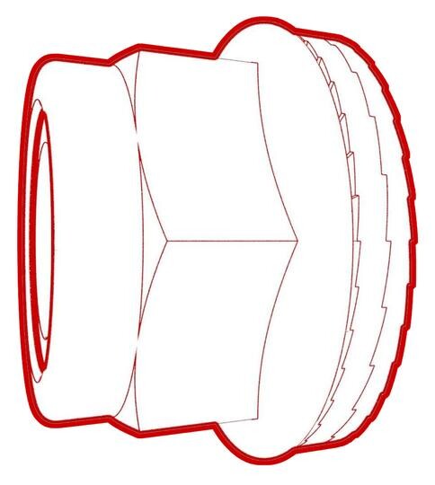
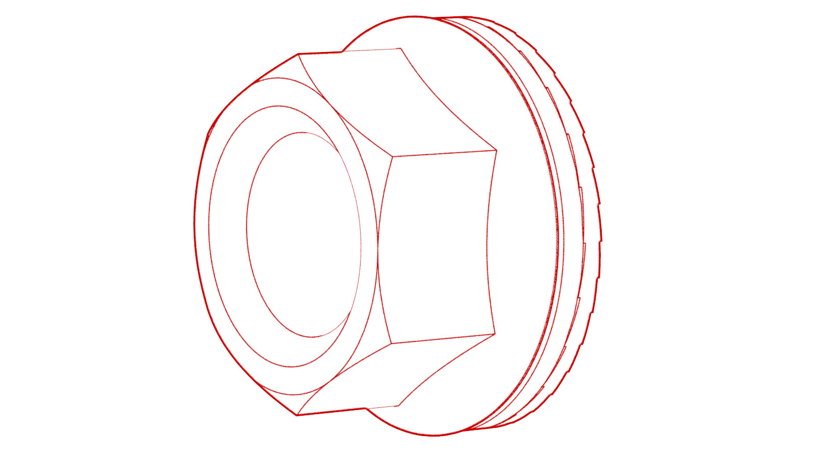
Position the axle remover cable around the inner joint of the LH front drive unit halfshaft, and then use a cable tie to hold the axle remover cable in position.
Figure 1. Axle removed from drive unit for demonstration purposes -
Hook the axle remover slide hammer on the 2 axle remover cable loops, and then use the slide hammer to remove the halfshaft from the drive unit.
NoteMove the LH front knuckle assembly aside to provide enough clearance to safely remove the LH front drive unit halfshaft.
Install
-
Apply approximately 1 gram
of Molykote M-77 Lubricant Paste only to the hub
mating face on the outboard side of the LH front drive unit halfshaft.
CAUTIONDo not apply any lubricant to the halfshaft splines. If lubricant is mistakenly applied, wipe the splines clean with a shop towel.
-
With assistance, install the
LH front drive unit halfshaft into the front drive unit.
NoteMove the LH front knuckle assembly aside to provide enough clearance to safely install the LH front drive unit halfshaft.CAUTIONTake care not to damage or displace the oil seal.CAUTIONMake sure that the opening of the snap ring is facing towards the bottom of the drive unit.
-
Verify that the halfshaft is fully seated:
- Carefully push the halfshaft into the drive unit until there is an audible "click" from the halfshaft stub contacting the pinion shaft.
- There will be a slight pulling sensation on the halfshaft as the halfshaft circlip locks into place.
- Pull on the inner halfshaft cup to confirm that the circlip is locked into place. If the halfshaft detaches from the drive unit then reinstall the halfshaft and then test that it is fully seated.
- Align the splines of the LH front halfshaft with those of the LH front hub, and then install the halfshaft into the hub.
-
Install only the axle nut onto the
halfshaft, and then use a ratchet and socket to manually tighten the nut to pull the
halfshaft into the hub until it seats.
NoteDo not use power tools to tighten the nut as it might strip the threads.
-
Remove the axle nut from the halfshaft,
install a new washer onto the halfshaft, and then reinstall the axle nut hand
tightened.
NoteThe axle nut is torqued in a later step.
-
Hand-tighten the bolt and nut that attach the LH strut to the LH front lower lateral link.
-
Install the bolt and nut that attach the LH front upper control arm to the LH front knuckle.
 56 Nm (41.3 lbs-ft)TIpUse of the following tool(s) is recommended:
- Torx Plus T47 socket
- 15mm combination wrench
-
Install the new nyloc nut that attaches the LH tie rod end to the LH front knuckle.
 180 Nm (132.7 lbs-ft)TIpUse of the following tool(s) is recommended:
- 22 mm socket
- 22mm combination wrench
- 10mm combination wrench
-
Install the clips that attach the LH front ABS wheel speed
sensor to the LH front knuckle.
-
Install the bolt that
attaches the LH front ABS wheel speed sensor to the LH front knuckle.
 5 Nm (3.7 lbs-ft)TIpUse of the following tool(s) is recommended:
- 10 mm deep socket
- Flex head ratchet/flex head torque wrench
- 4 in extension
- Install the LH front wheel and hand-tighten the wheel lug nuts.
- Lower the vehicle until the tires are touching the ground. See Raise Vehicle - 2 Post Lift.
- Fully tighten the wheel lug nuts. See Wheel Assembly (Remove and Install).
-
Fully tighten the new LH
front drive unit halfshaft nut and washers.
 300 Nm (221.2 lbs-ft)NoteThe washers are attached to the nut.TIpUse of the following tool(s) is recommended:
- 32mm deep impact long socket
- Install the wheel center cap. See Cap - Wheel (Remove and Replace).
- Remove the vehicle from the lift and drive the vehicle onto an alignment rack.
-
Fully tighten the bolt and nut that attach the LH strut to the LH front lower lateral link, and then mark the bolt and nut with a paint pen.
 106 Nm (78.2 lbs-ft)
 106 Nm (78.2 lbs-ft)TIpUse of the following tool(s) is recommended:
- 21 mm socket
- 21mm combination wrench