Glove Box (Remove and Replace)
 Correction code
14051002
0.48
NOTE: Unless otherwise explicitly
stated in the procedure, the above correction code and FRT reflect all of the work
required to perform this procedure, including the linked procedures. Do not stack correction codes unless
explicitly told to do so.
NOTE: See Flat Rate Times to learn
more about FRTs and how they are created. To provide feedback on FRT values, email ServiceManualFeedback@tesla.com.
NOTE: See Personal Protection to make sure proper PPE is worn when
performing the below
procedure.
Correction code
14051002
0.48
NOTE: Unless otherwise explicitly
stated in the procedure, the above correction code and FRT reflect all of the work
required to perform this procedure, including the linked procedures. Do not stack correction codes unless
explicitly told to do so.
NOTE: See Flat Rate Times to learn
more about FRTs and how they are created. To provide feedback on FRT values, email ServiceManualFeedback@tesla.com.
NOTE: See Personal Protection to make sure proper PPE is worn when
performing the below
procedure.
Remove
- Open the RH front door and lower the RH front window.
- Move the front passenger forward.
- Remove the RH mid A-pillar trim. See Trim - A-Pillar - Middle - LH (Remove and Replace).
- Remove the RH instrument panel end cap. See End Cap - Instrument Panel - LH (Remove and Replace).
- Use the vehicle touchscreen to open the glove box.
- Remove the rear underhood apron. See Underhood Apron - Rear (Remove and Replace).
- Disconnect LV power. See LV Power (Disconnect and Connect).
- Remove the RH instrument panel middle trim. See Trim - Middle - Instrument Panel - RH (Remove and Replace).
- Remove the passenger footwell cover. See Cover - Footwell - Passenger (Remove and Replace).
-
Remove and discard the patch bolts
(x2) that attach the front passenger knee airbag assembly to the instrument panel.
TIpUse of the following tool(s) is recommended:
- 2 in extension
- Ratchet/torque wrench
- External Torx E10
- ¼ in to 3/8 in adapter
-
Release the tabs (x6) that attach the
front passenger knee airbag assembly to the instrument panel, and then partially lower
the airbag.
NoteThe front passenger knee airbag is still connected to the vehicle. Be careful not to damage the electrical connectors when lowering the airbag from the instrument panel.
-
Disconnect the electrical connectors
(x2) from the front passenger knee airbag assembly.
NoteThe front passenger knee airbag has 2 locking tabs.TIpUse of the following tool(s) is recommended:
- Pick Miniature Soft Grip, 90 degree tip, 6 in
-
Remove the screws (x5) that attach the
glove box to the vehicle, and then release the glove box from the instrument panel.
 3 Nm (2.2 lbs-ft)CAUTIONDo not pull the glove box assembly too far away from the instrument panel as there are connectors still connected.TIpUse of the following tool(s) is recommended:
- T20 socket
-
Disconnect the glove box electrical
connectors (x3).
-
Remove the screws (x2) and release the
clip that attach the USB outlet to the glove box assembly, and then remove the outlet
from the glove box assembly.3 Nm (2.2 lbs-ft)TIpUse of the following tool(s) is recommended:
- T20 socket
-
Remove the glove box assembly from the
vehicle.
-
Remove the screws (x4) that attach the
inboard and outboard shape memory alloy (SMA) locator plates to the glove box assembly,
and then remove the plates from the assembly.2 Nm (1.5 lbs-ft)TIpUse of the following tool(s) is recommended:
- T20 socket
-
Remove the screws (x2) that attach the
glove box shape memory alloy (SMA) latch to the glove box assembly, and then release the
SMA from the assembly.2 Nm (1.5 lbs-ft)TIpUse of the following tool(s) is recommended:
- T20 socket
-
Route the glove box shape memory alloy
(SMA) latch manual release cable out of the glove box housing, release the harness from
the mounting points (x2), and then lift the SMA assembly out of the glove box.
Install
-
Route the glove box shape memory alloy
(SMA) latch manual release cable into glove box housing, secure the harness into the
mounting points (x2), and then insert the SMA assembly arms into the glove box
door.
-
Position the glove box shape memory
alloy (SMA) latch assembly into the glove box assembly, and then install the screws (x2)
that attach the SMA to the glove box assembly.2 Nm (1.5 lbs-ft)TIpUse of the following tool(s) is recommended:
- T20 socket
-
Position the inboard and outboard
shape memory alloy (SMA) locator plates to the glove box assembly, and then install the
screws (x4) that attach the plates to the assembly.2 Nm (1.5 lbs-ft)TIpUse of the following tool(s) is recommended:
- T20 socket
-
Position the USB outlet into the glove
box, and then install the screws (x2) and secure the clip that attaches the outlet to
the glove box.3 Nm (2.2 lbs-ft)NoteMake sure the USB socket is flush in the glove box.TIpUse of the following tool(s) is recommended:
- T20 socket
-
Connect the glove box electrical
connectors (x3).
-
Position the glove box into the instrument panel, and then install the screws (x5)
that attach the glove box to the instrument panel.3 Nm (2.2 lbs-ft)NoteInstall the screws at the top of the glove box first, and then close the lid to install the bottom screws. Use the manual release to open glove box if needed.TIpUse of the following tool(s) is recommended:
- T20 socket
-
While supporting the front passenger
knee airbag assembly, connect the electrical connectors (x2).
CAUTIONCarefully connect the airbag electrical connector to prevent damage to the electrical connectors.
- Hook the tabs (x6) before putting the front passenger knee airbag onto the instrument panel, and then seat the airbag to the instrument panel.
-
Install the new patch bolts (x2) that
attach the front passenger knee airbag to the instrument panel.
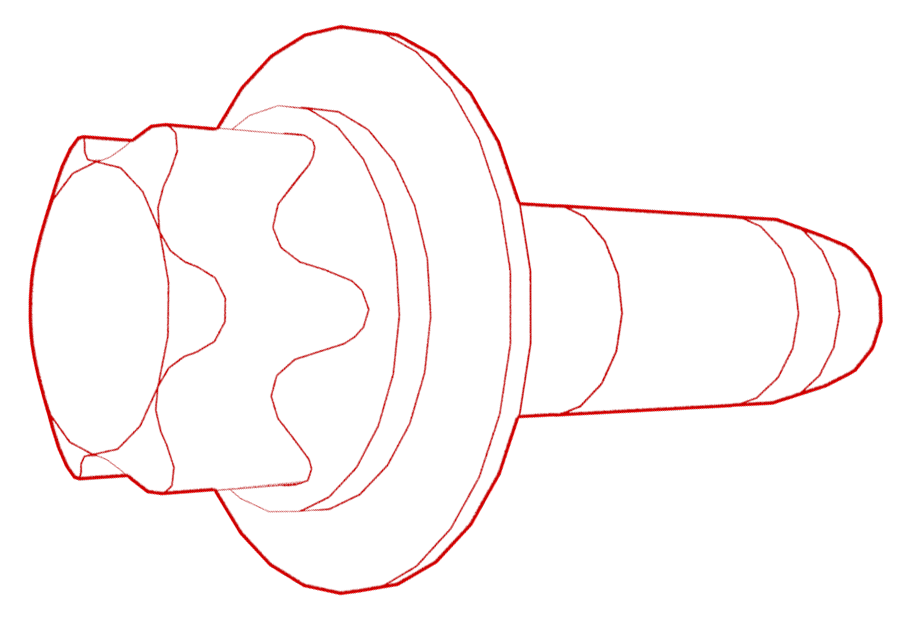 8 Nm (5.9 lbs-ft)TIpUse of the following tool(s) is recommended:
- 2 in extension
- Ratchet/torque wrench
- External Torx E10
- ¼ in to 3/8 in adapter
- Install the passenger footwell cover. See Cover - Footwell - Passenger (Remove and Replace).
- Install the RH instrument panel middle trim. See Trim - Middle - Instrument Panel - RH (Remove and Replace).
- Connect LV power. See LV Power (Disconnect and Connect).
- Install the rear underhood apron. See Underhood Apron - Rear (Remove and Replace).