2023-08-25
Control Arm - Upper - Front - LH (Remove and Replace)
 Correction code
31014002
0.84
NOTE: Unless otherwise explicitly
stated in the procedure, the above correction code and FRT reflect all of the work
required to perform this procedure, including the linked procedures. Do not stack correction codes unless
explicitly told to do so.
NOTE: See Flat Rate Times to learn
more about FRTs and how they are
created.
NOTE: See Personal Protection to make sure proper PPE is worn when
performing the below
procedure.
Correction code
31014002
0.84
NOTE: Unless otherwise explicitly
stated in the procedure, the above correction code and FRT reflect all of the work
required to perform this procedure, including the linked procedures. Do not stack correction codes unless
explicitly told to do so.
NOTE: See Flat Rate Times to learn
more about FRTs and how they are
created.
NOTE: See Personal Protection to make sure proper PPE is worn when
performing the below
procedure.
Torque Specifications
| Description | Torque Value | Recommended Tools | Reuse/Replace | Notes |
|---|---|---|---|---|
| Bolt and nut that attach the front upper control arm to the knuckle |
 60 Nm (44.2 lbs-ft) |
|
Reuse Replace | Reuse the bolt, replace the nut; PN - 1111145-00-A |
| Bolt that attaches the wheel speed sensor bracket to the front upper control arm |
 5 Nm (3.7 lbs-ft) |
|
Reuse | |
| Bolt that attaches the ride height sensor to the front upper control arm |
 7 Nm (5.2 lbs-ft) |
|
Reuse | |
| Bolts (x2) that attach the front upper control arm to the vehicle |
 68 Nm (50.1 lbs-ft) |
|
Reuse |
Remove
- On the touchscreen, touch to enable Jack Mode.
- On the touchscreen, touch to power off the center display.
- Raise and support the vehicle. See Raise Vehicle - 2 Post Lift.
- Remove the rear underhood apron. See Underhood Apron - Rear (Remove and Replace).
- Disconnect LV power. See LV Power (Disconnect and Connect).
- Remove the LH and RH underhood aprons. See Underhood Apron - LH (Remove and Replace).
- Remove the LH and RH wiper arms. See Wiper Arm - LH (Remove and Replace).
- Remove the LH and RH shock tower covers. See Cover - Shock Tower - LH (Remove and Replace).
- Remove the cowl screen panel. See Panel - Cowl Screen (Remove and Replace).
- Remove the battery controller. See Module - Battery Controller (Remove and Replace).
- Remove the LH front wheel. See Wheel Assembly (Remove and Install).
-
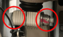
Remove the bolt that attaches the
wheel speed sensor bracket to the front upper control arm.
TIpUse of the following tool(s) is recommended:
- 10 mm socket
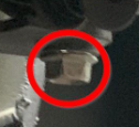
-
Remove the bolt that attaches the ride
height sensor to the upper control arm and pivot the ride height sensor away from the
upper control arm.
TIpUse of the following tool(s) is recommended:
- 10 mm socket
- 9 mm combination wrench
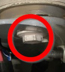
-
Remove the nut that attaches the LH
knuckle to the upper control arm ball joint.
NoteHold the bolt in place to prevent turning while removing the nut. Discard the nut after removal.TIpUse of the following tool(s) is recommended:
- 15 mm combination wrench
- Torx T50 socket
-
Remove the bolt that attaches the LH
knuckle to the upper control arm.
NoteSupport the knuckle as the ball joint is released.TIpUse of the following tool(s) is recommended:
- 15 mm combination wrench
- Torx T50 socket
- Lower the vehicle until the tires are touching the ground.
-
Remove the bolts (x2) that attach the
LH front upper control arm to the vehicle, and then remove control arm from the
vehicle.
TIpUse of the following tool(s) is recommended:
- 15 mm socket
Install
-
Install and hand-tighten the bolts
(x2) that attach the LH front upper control arm to the vehicle.
TIpUse of the following tool(s) is recommended:
- 15 mm socket
- Raise the vehicle fully.
-
Using a new patch nut, install the LH
upper control arm ball joint to the LH front knuckle.60 Nm (44.2 lbs-ft)TIpUse of the following tool(s) is recommended:
- 15 mm combination wrench
- Torx T50 socket
-
Install the bolt that attaches the
front LH ride height sensor to the control arm.7 Nm (5.2 lbs-ft)NoteUse a 9mm wrench to counter hold the ball joint pin while tightening the lock nut.TIpUse of the following tool(s) is recommended:
- 10 mm socket
- 9 mm combination wrench
-
Install the bolt that attaches the
wheel speed sensor bracket to the front upper control arm.5 Nm (3.7 lbs-ft)TIpUse of the following tool(s) is recommended:
- 10 mm socket
-
Torque the bolts (x2) that attach the
LH front upper control arm to the vehicle.68 Nm (50.1 lbs-ft)TIpUse of the following tool(s) is recommended:
- 15 mm socket
- Install the LH front wheel. See Wheel Assembly (Remove and Install).
- Install the battery controller. See Module - Battery Controller (Remove and Replace).
- Install the cowl screen panel. SeePanel - Cowl Screen (Remove and Replace).
- Install the LH and RH shock tower covers. See Cover - Shock Tower - LH (Remove and Replace).
- Connect LV power. See LV Power (Disconnect and Connect).
- Install the LH and RH underhood aprons. See Underhood Apron - LH (Remove and Replace).
- Install the rear underhood apron. See Underhood Apron - Rear (Remove and Replace).
- On the touchscreen, touch to disable Jack Mode.
- Refer to the Alignment Requirement tables to determine whether an EPAS alignment check (EC) or four wheel alignment check (AC) is necessary. If performed, add the alignment check/adjust as a separate activity. See Alignment Requirement - Suspension.