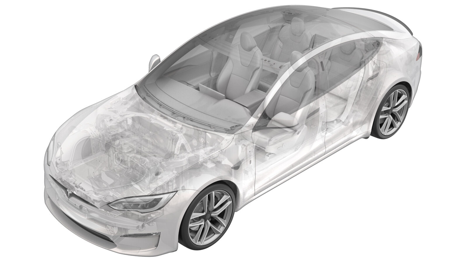
Car Computer (HW4) (Remove and Install)
 Correction code
21151031
0.48
NOTE: Unless
otherwise explicitly stated in the procedure, the above correction code and
FRT reflect all of the work required to perform this procedure, including
the linked procedures. Do
not stack correction codes unless explicitly told to do so.
NOTE: See Flat Rate Times to learn more about FRTs and how
they are created. To provide feedback on FRT values, email ServiceManualFeedback@tesla.com.
NOTE: See Personal Protection
to make sure wearing proper PPE when performing the below procedure.
NOTE: See Ergonomic Precautions for safe and
healthy working practices.
- 2023-09-06: Cleaned up procedure.
- 1135762-00-A Kit, Service Plugs, Cooling Hose
- 1119171-00-A Car Computer Fluid Port Plug
Remove
- Open both front doors and lower both front windows.
-
Move the front passenger seat fully
rearwards.
- Disconnect LV power. See LV Power (Disconnect and Connect).
- Remove the RH middle A-pillar trim. See Trim - A-Pillar - Middle - LH (Remove and Replace).
- Remove the RH lower A-pillar trim. See Trim - A-Pillar - Lower - LH (Remove and Replace).
- Remove the passenger footwell cover. See Cover - Footwell - Passenger (Remove and Replace).
-
Remove the front passenger floor
mat.
- Remove the RH center console side panel carpet. See Carpet - Side Panel - Center Console - LH (Remove and Replace).
- Remove the front passenger footrest panel. See Panel - Footrest - Front Passenger (LHD) (Remove and Replace).
-
Disconnect the electrical connector to
the connectivity module.
NoteMove the release lock rearward before removal.
-
Disconnect the electrical connectors
(x6) at the RH side of the infotainment motherboard.
NoteRelease the lock on each electrical connector before removal.
-
Disconnect the electrical connectors
(x3) at the RH side of the Autopilot motherboard.
NoteRelease the lock on each electrical connector before removal.
-
Disconnect the electrical connectors
(x7) at the LH side of the infotainment motherboard.
NoteRelease the lock on each electrical connector before removal.
-
Disconnect the electrical connectors
(x5) at the LH side of Autopilot motherboard.
NoteRelease the lock on each electrical connector before removal.
-
Install coolant hose clamps (x2) to
the coldplate hoses of the car computer.
NotePlace coolant absorbent material around the car computer.
-
Release the spring locks (x2) that
attach each coolant hoses (x2) to the car computer coldplate assembly.
NoteInstall coolant plugs at both hoses and car computer upon hose removal.
-
Move the absorbent mat aside to clear
the car computer area.
NoteWipe away excess coolant from the floor.
-
Remove the bolts (x2) and nuts (x2)
that attach the car computer to the body, and then remove the car computer from the
vehicle.
Torque specifications:
- for the bolts: 8 Nm
- for the nuts: 7 Nm
TIpUse of the following tool(s) is recommended:- 10 mm socket
NoteRemove any residual coolant from the vehicle.
Install
-
Install the bolts (x2) and nuts (x2)
that attach the car computer to the body.
Torque specifications:
- for the bolts: 8 Nm
- for the nuts: 7 Nm
TIpUse of the following tool(s) is recommended:- 10 mm socket
-
Remove the coolant plugs from the
hoses (x2), secure the coolant hoses onto the car computer coldplate assembly, and then
secure them with spring locks (x2).
NotePlace absorbent material onto the car computer.
-
Remove the coolant hose clamps from
the hoses (x2).
NoteRemove absorbent material.NoteClean residual fluid.NoteInspect for coolant leaks.
-
Connect the electrical connectors (x5)
onto the LH side of the Autopilot motherboard.
NoteSecure the locks on the electrical connectors after installation.
-
Connect the electrical connectors (x7)
onto the LH side of the infotainment motherboard.
NoteSecure the locks on the electrical connectors after installation.
-
Connect the electrics connectors (x3)
onto the RH side of the Autopilot motherboard.
-
Connect the electrical connectors (x6)
onto the RH side of the infotainment motherboard.
NoteSecure the locks on the electrical connectors after installation.
-
Install the electrical connector to
the connectivity module.
NoteSlide the lock underneath the electrical connector.
- Connect LV power. See LV Power (Disconnect and Connect).
- Perform a cooling system partial refill and bleed. See Cooling System (Partial Refill and Bleed).
- Install the rear underhood apron. See Underhood Apron - Rear (Remove and Replace).
- Close the hood.
- Install the front passenger footrest panel. See Panel - Footrest - Front Passenger (LHD) (Remove and Replace).
- Install the RH center console side panel carpet. See Carpet - Side Panel - Center Console - LH (Remove and Replace).
- Install the passenger footwell cover. See Cover - Footwell - Passenger (Remove and Replace).
-
Install the front passenger floor
mat.
- Install the RH lower A-pillar trim. See Trim - A-Pillar - Lower - LH (Remove and Replace).
- Install the RH middle A-pillar trim. See Trim - A-Pillar - Middle - LH (Remove and Replace).
-
Restore the front passenger seat back
to its original position.
- Raise both front windows and close both front doors.