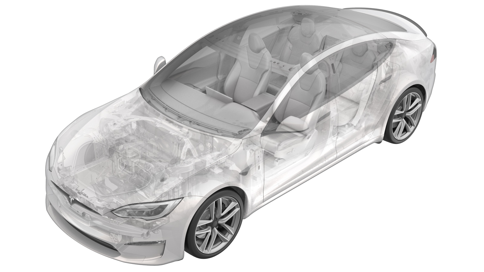
Cooling System (Vacuum Refill)
 Correction code
18300400
0.40
NOTE: Unless otherwise explicitly
stated in the procedure, the above correction code and FRT reflect all of the work
required to perform this procedure, including the linked procedures. Do not stack correction codes unless
explicitly told to do so.
NOTE: See Flat Rate Times to learn
more about FRTs and how they are created. To provide feedback on FRT values, email ServiceManualFeedback@tesla.com.
NOTE: See Personal Protection to make sure proper PPE is worn when
performing the below
procedure.
- 1050448-00-B Refiller, Cooling System
Procedure
-
Perform the following
routine using Service Mode or Toolbox (see 0005 - Service Modes):
PROC_VCFRONT_X_START-THERMAL-FILL-DRAIN-COOLANTvia Toolbox: (link)via Service Mode Plus:
- Drive Inverter ➜ Front Drive Inverter Replacement ➜ Start Fluid Fill/Drain
- Drive Inverter ➜ Rear Drive Inverter Replacement ➜ Start Fluid Fill/Drain
- Drive Inverter ➜ Rear Left Drive Inverter Replacement ➜ Start Fluid Fill/Drain
- Drive Inverter ➜ Rear Right Drive Inverter Replacement ➜ Start Fluid Fill/Drain
- Drive Unit ➜ Front Drive Unit Replacement ➜ Start Coolant Fill/Drain
- Drive Unit ➜ Rear Drive Unit Replacement ➜ Start Coolant Fill/Drain
NoteVerify the vehicle is in Series via Garage > Vitals > Thermal tab > Coolant loops, Thermal Fluid Fill/Drain.NoteThe routine has a 5 hour limit. After 5 hours, the routine must be performed again. -
Disconnect the laptop from the
vehicle.
NoteDo not close Toolbox because the routine will resume later.
- Remove the rear underhood apron. See Underhood Apron - Rear (Remove and Replace).
- Disconnect LV power. See LV Power (Disconnect and Connect).
-
Remove the coolant bottle cap.
- Put an empty coolant container in the underhood storage unit.
- Fill another container with at least 15L of coolant.
- Put the filled coolant container next to the empty coolant container in the underhood storage unit.
-
Install the vacuum refill cap onto the
coolant bottle assembly.
-
Setup the coolant refill tool.
NoteVerify all valves on the refill tool are in the closed position.
-
Install the vacuum refill hose into
the refill cap on the coolant bottle.
NotePerform a push-pull-push test to verify that the hose is fully installed.
-
Put the refill hose inside the filled
coolant container.
NoteMake sure the hose end is fully submerged in coolant.
-
Position the overflow hose in the
empty container.
-
Connect shop air supply to the coolant
refill tool.
NoteIf not already done, verify that the refill valve is set to off.
-
Open the air inlet valve to draw a
vacuum. Once the gauge stabilizes, close the valve fully.
NoteThe gauge stabilizes roughly at 60-70 cmHg. Vacuum should not drop after the valves are closed.
-
Slowly open the refill valve to allow
coolant to be drawn into the cooling system.
NoteMake sure the hose end of refill hose is fully submerged during entire process.
-
Once the gauge reads zero, close the
coolant refill valve.
- Remove the coolant refill hose from the coolant container.
- Remove the coolant overflow hose from the coolant container.
-
Remove the vacuum refill hose from the
refill cap on the coolant bottle.
-
Remove the vacuum refill tool
cap.
- Remove the coolant refill tool from the vehicle.
-
Remove both coolant containers from
the underhood storage unit area.
- Connect LV power. See LV Power (Disconnect and Connect).
-
Perform the following
routine using Service Mode or Toolbox (see 0005 - Service Modes):
TEST_VCFRONT_X_THERMAL-COOLANT-AIR-PURGEvia Toolbox: (link)via Service Mode:
- Thermal ➜ Actions ➜ Coolant Purge Stop or Coolant Purge Start
- Thermal ➜ Coolant System ➜ Coolant Purge Start
- Drive Inverter ➜ Front Drive Inverter Replacement ➜ Coolant Air Purge
- Drive Inverter ➜ Rear Drive Inverter Replacement ➜ Coolant Air Purge
- Drive Inverter ➜ Rear Left Drive Inverter Replacement ➜ Coolant Air Purge
- Drive Inverter ➜ Rear Right Drive Inverter Replacement ➜ Coolant Air Purge
- Drive Unit ➜ Front Drive Unit Replacement ➜ Coolant Air Purge
- Drive Unit ➜ Rear Drive Unit Replacement ➜ Coolant Air Purge
CAUTIONMake sure the vehicle is not in drive. The test runs for approximately 10 minutes. Putting vehicle into a drive state will stop this routine. Monitor the coolant level and add more coolant as needed.NoteThis test is still running despite the stop message.NoteThe coolant pumps will be audible during this test. -
Perform the following
routine using Service Mode or Toolbox (see 0005 - Service Modes):
TEST-SELF_VCFRONT_X_THERMAL-PERFORMANCEvia Toolbox: (link)via Service Mode: Thermal ➜ Actions ➜ Test Thermal Performancevia Service Mode Plus:
- Drive Inverter ➜ Front Drive Inverter Replacement ➜ Thermal System Test
- Drive Inverter ➜ Rear Drive Inverter Replacement ➜ Thermal System Test
- Drive Inverter ➜ Rear Left Drive Inverter Replacement ➜ Thermal System Test
- Drive Inverter ➜ Rear Right Drive Inverter Replacement ➜ Thermal System Test
- Drive Unit ➜ Front Drive Unit Replacement ➜ Thermal System Test
- Drive Unit ➜ Rear Drive Unit Replacement ➜ Thermal System Test
-
Check the coolant level and top off as
needed.
NoteUse a mirror to aid visually.NoteMake sure the coolant fluid level is at the Max line and top off as needed.
-
Install the coolant bottle cap.
- Install the rear underhood apron. See Underhood Apron - Rear (Remove and Replace).