2025-10-20
Module - Body Controller - Front (2025+) (Remove and Replace)
 Correction code
TBD
FRT
0.54
NOTE: Unless otherwise explicitly stated in the procedure, the correction code and FRT listed above reflect all of the work required to perform this procedure, including the linked procedures. Do not stack correction codes unless explicitly told to do so.
NOTE: See Flat Rate Times to learn more about FRTs and how they are created.
NOTE: See Personal Protection to make sure you
are wearing proper PPE when performing the procedure below.
NOTE: See Ergonomic Precautions for safe and healthy working practices.
Correction code
TBD
FRT
0.54
NOTE: Unless otherwise explicitly stated in the procedure, the correction code and FRT listed above reflect all of the work required to perform this procedure, including the linked procedures. Do not stack correction codes unless explicitly told to do so.
NOTE: See Flat Rate Times to learn more about FRTs and how they are created.
NOTE: See Personal Protection to make sure you
are wearing proper PPE when performing the procedure below.
NOTE: See Ergonomic Precautions for safe and healthy working practices.
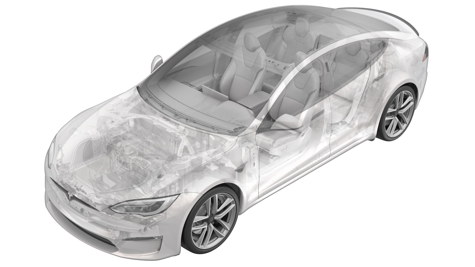
Note
This procedure describes work that is
specific to 2025+ Model S.
Remove
- Open the LH front door and lower the LH front window.
- Remove the rear underhood apron. See Underhood Apron - Rear (Remove and Replace).
- Disconnect LV power. See LV Power (Disconnect and Connect).
- Remove the underhood storage unit. See Underhood Storage Unit (Remove and Replace).
-
Release the upper locking connectors (x2) on the front body controller module.
NotePush in locking tabs, and then lift the levers to release.
-
Release the LH middle locking connector on the front body controller module.
NotePush in locking tab, and then lift the lever to release.
-
Release the RH middle locking connectors (x2) on the front body controller
module.
NoteSlide the locking mechanism outwards to release.
-
Release the lower locking connectors (x2) on the front body controller module.
NoteSlide the red locking tab outwards to release.
-
Remove the bolt that attaches the ground cable to the front body controller
module.
TIpUse of the following tool(s) is recommended:
- Socket 1/4in Dr. 6pt. Deep x 10mm
-
Remove the bolts (x3) that attach the front body controller module to the body.
TIpUse of the following tool(s) is recommended:
- Socket 1/4in Dr. 6pt. Deep x 10mm
-
Release the locking tabs (x2) that attach the front body controller to the vehicle,
disconnect the ground cable from the multi-system beam, and then remove the front body
controller.
Install
-
Position front controller for installation, connect the ground cable to the
multi-system beam, and secure the locking tabs (x2) that attach the front body
controller to the vehicle.
-
Install the bolts (x3) that attach the front body controller module to the body.
 10 Nm (7.4 lbs-ft)NoteStart with the side bolt.TIpUse of the following tool(s) is recommended:
- Socket 1/4in Dr. 6pt. Deep x 10mm
-
Install the bolt that attaches the ground cable to the front body controller
module.10 Nm (7.4 lbs-ft)TIpUse of the following tool(s) is recommended:
- Socket 1/4in Dr. 6pt. Deep x 10mm
-
Secure the lower locking connectors (x2) on the front body controller module.
NoteEngage the red locking tab.
-
Secure the RH middle locking connectors (x2) on the front body controller
module.
NoteVerify that the yellow locking tabs are fully opened. Seat connectors and mechanism will begin to engage.
-
Secure the LH locking connector for the front body controller module.
NoteVerify the lever is fully opened. Seat connector and lever will begin to engage.
-
Secure the upper locking connectors (x2) for the front body controller module.
NoteVerify levers are fully opened. Seat connectors and levers will begin to engage.
- Connect LV power. See LV Power (Disconnect and Connect).
-
Perform the following
routine using Service Mode or Toolbox (see 0005 - Service Modes):
-
UPDATE_CAN-REDEPLOYvia Service Mode Plus:
- Drive Inverter Replacement ➜ Drive Inverter DIRE1L Replacement ➜ CAN Redeploy
- Drive Inverter Replacement ➜ Drive Inverter DIRE1R Replacement ➜ CAN Redeploy
- Drive Inverter Replacement ➜ Drive Inverter DIRE2 Replacement ➜ CAN Redeploy
- Drive Inverter ➜ Front Drive Inverter Replacement ➜ CAN Redeploy
- Drive Inverter ➜ Rear Drive Inverter Replacement ➜ CAN Redeploy
- Drive Inverter ➜ Rear Left Drive Inverter Replacement ➜ CAN Redeploy
- Drive Inverter ➜ Rear Right Drive Inverter Replacement ➜ CAN Redeploy
- Drive Unit ➜ Front Drive Unit Replacement ➜ CAN Redeploy
- Drive Unit ➜ Rear Drive Unit Replacement ➜ CAN Redeploy
- Thermal ➜ HVAC ➜ CAN Redeploy
- chassis ➜ DPB Post Replacement ➜ CAN Redeploy
- chassis ➜ ESP Post Replacement ➜ CAN Redeploy
- chassis ➜ IDB Post Replacement ➜ CAN Redeploy
- chassis ➜ RCU Post Replacement ➜ CAN Redeploy
- chassis ➜ ESP Replacement Panel ➜ CAN Redeploy
- chassis ➜ IBST Replacement Panel ➜ CAN Redeploy
- PROC_VCFRONT_X_POST-REPLACEMENT-PROCEDUREvia Service Mode Plus:low-voltage ➜ VCFRONT Post Replacement ➜ VCFRONT Post Replacement Procedurevia Toolbox:(link)
-
UPDATE_CAN-REDEPLOYvia Service Mode Plus:
- Exit Service Mode or disconnect the laptop if applicable (see 0005 - Service Modes).
- Adjust the headlights. See Headlights - Adjust - NA (Wall Method) or Headlights - Adjust - NA (Tool Method).
- Install the underhood storage unit. See Underhood Storage Unit (Remove and Replace).
- Raise the LH front window and close the LH front door.