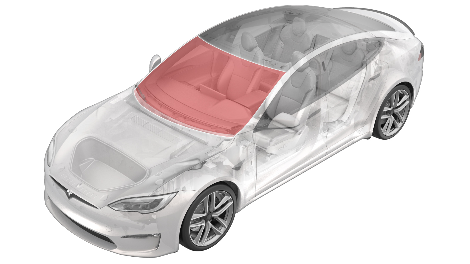
Windshield (Remove and Install)
 Correction code
10200301
2.10
NOTE: Unless otherwise explicitly
stated in the procedure, the above correction code and FRT reflect all of the work
required to perform this procedure, including the linked procedures. Do not stack correction codes unless
explicitly told to do so.
NOTE: See Flat Rate Times to learn
more about FRTs and how they are
created.
NOTE: See Personal Protection to make sure proper PPE is worn when
performing the below
procedure.
Correction code
10200301
2.10
NOTE: Unless otherwise explicitly
stated in the procedure, the above correction code and FRT reflect all of the work
required to perform this procedure, including the linked procedures. Do not stack correction codes unless
explicitly told to do so.
NOTE: See Flat Rate Times to learn
more about FRTs and how they are
created.
NOTE: See Personal Protection to make sure proper PPE is worn when
performing the below
procedure.
- 2026-06-10: Added warning notes to set drill clutch to 1 before using with Spider tool.
- 2023-08-17: Updated removal tool.
- 2024-04-11: Added a step of cleaning the windshield, especially the forward-facing camera area, to ensure a clear view of the forward-facing camera.
Remove
- Open the LH front door and lower the LH front window.
- Remove the rear underhood apron. See Underhood Apron - Rear (Remove and Replace).
- Remove the LH and RH underhood aprons. See Underhood Apron - LH (Remove and Replace).
- Remove the LH and RH wiper arms. See Wiper Arm - LH (Remove and Replace).
- Remove the LH and RH shock tower covers. See Cover - Shock Tower - LH (Remove and Replace).
- Remove the cowl screen panel. See Panel - Cowl Screen (Remove and Replace).
- Remove the LH middle A-pillar trim. See Trim - A-Pillar - Middle - LH (Remove and Replace).
- Remove the LH IP end cap. See End Cap - Instrument Panel - LH (Remove and Replace).
- Remove the LH upper A-pillar trim. See Trim - A-Pillar - Upper - LH (Remove and Replace).
- Remove the driver sun visor. See Sun Visor - LH (Remove and Replace).
- Repeat step 7through step 10 for the RH side of the vehicle.
-
Disconnect the heated wiper area
electrical connector, and then tape the connector to the windshield, if equipped.
- Remove the rear view mirror. See Mirror - Rear View (Remove and Replace).
- Remove the upper camera cover. See Upper Cover - Rear View Mirror (Remove and Replace).
-
Disconnect the harness electrical
connector from the humidity and temperature sensor on the windshield.
-
Disconnect the harness electrical
connector for the fan.
-
Disconnect the harness electrical
connector for the heated camera area.
-
Disconnect the harness electrical
connector for the GPS/GNSS antenna.
-
Remove the clips (x2) that attach the
triple cam hood to the windshield, and remove it from the windshield.
-
Disconnect the humidity sensor
electrical connector.
-
Remove the screws (x4) that attach the
mounting plate to the windshield and allow the camera to hang by the harness.
 0.8 Nm (7 lbs-in)TIpUse of the following tool(s) is recommended:
- Torx T10 bit
-
Disconnect the camera harness
electrical connectors (x2), and then remove the assembly from the vehicle.
-
Tape the fan and heater grid
electrical connector onto the windshield.
NotePrevent the wires from being accidentally cut.
-
Release the clips (x5) that attach the
front of the headliner to the vehicle.
-
Tape the front of the headliner as a
precautionary measure.
-
Apply masking tape to the exterior of
the LH and RH A-pillars to protect the paint from damage.
-
Prepare WRD Spider 3 glass removal
kit
-
Secure line to starter tool and push
tool through urethane at lower RH side of windshield
NoteUse the guard to prevent damage to dash pad while using starter tool
-
Release line from starter tool and
wrap line around exterior of windshield
NotePull line away from starter tool, Ensure enough length is pulled through, Wrap spider line up and around the exterior of windshield, Verify the line sits underneath the glass
-
Attach anchor point to exterior of
windshield and secure line
NoteAttach line to anchor once fully wrapped around windshield, Place anchor near starting point of the handle tool
-
Secure interior side of line to the
spider cutting tool
NoteFollow instructions on spider tool, Feed line through opening of the cutting tool and tie a knot to secure in place, If spindle is not turned the proper direction the cutting tool will be damaged
-
Secure spider cutting tool to interior
side of windshield
NoteNote orientation of the cutting line, Make sure line warps over large pulley and holds at a 90 degree angle
-
Install an angle driver to an electric drill and set the drill clutch to 1.
WarningFailure to set the drill clutch to 1 may result in serious injury.
-
Turn the spindle on the cutting tool
with the drill to start removing the windshield.
WarningDo not begin cutting the windshield without first setting the drill clutch to 1. Failure to do so may result in serious injury.WarningWear appropriate eye and hand protection while cutting the glass assembly.NoteUse caution around the two small datums at top of the windshield. Use protective material to prevent damage to the speaker grill and VIN plate.NoteMove the cutting tool as needed keeping the line close to a 90 degree angle, When passing VIN plate use guard to guide line over VIN to prevent damage.CAUTIONTake special care in the areas identified that have overlapping panels to prevent damage.
- Attach suction cups to the LH and RH sides of the windshield assembly.
-
With an assistant, remove the
windshield assembly from the vehicle.
NotePartially close the hood for clearance.
Install
- Remove the suction cups from the windshield assembly.
-
Inspect the windshield for any damage that is not reworkable.
NoteReplace the windshield if there is any damage that can not be rectified. Damages include: cracked glass, damaged heater grids, damaged/separating triple camera mount.
- Clean the windshield as needed. Take special caution to the forward-facing camera area to ensure a clear view of the forward-facing camera. See Clean Forward Camera View (Precision Cleaning of Inboard Glass).
-
Use a blade scraper to remove the old urethane from the vehicle.
- Remove the tape from the exterior of the LH and RH A-pillars.
-
Use a blade scraper to remove the urethane bead and windshield seals from the glass.
-
Use a permanent marker to draw an outline around the datums to assist in installation of the new datums.
-
Use a blade scraper to remove the damaged datums.
-
Use a blade scraper to remove the net pads (x3).
-
Use a blade scraper to clean any double sided tape residue.
NoteUse an eraser wheel if necessary.
- Clean all mating surfaces with Isopropyl Alcohol (IPA).
-
Measure the resistance of the wiper heater grid to check continuity.
NoteAll resistances @23degC. Tolerance +/-15%. Heated Wiper Area (HWA): 2.34ohms.
-
Install the windshield edge seal.
NoteFollow the windshield alignment marks at the lower corners of the glass.
-
Install the windshield lip seal.
NoteFollow the windshield alignment marks at the upper corners of glass. Start from one corner and peel the tape while applying the seal inch by inch to ensure proper fitment.
-
Install the net pads.
NoteUse the alignment marks on the glass for installation.
-
Install the LH and RH side datum.
-
With an assistant, position the windshield assembly onto the vehicle for a dry fit and note any locations where the pads need to be adjusted.
NoteVerify datums align properly. Ensure the heater grid harness is taped onto the glass to avoid contact with the urethane pathway and body.
-
Visually inspect the lip and edge seal.
NoteThe seal should be sitting against the vehicle body and look even all the way through.
- Remove the glass from the vehicle.
-
If necessary, perform the pad adjustment.
-
Clean the urethane path on the vehicle with an isopropyl alcohol (IPA) wipe. Allow the surface to dry before continuing to the next step.
NoteEnsure the inside of glass is clean and smudge free near the VIN plate as it won't be accessible once installed.
-
Apply urethane primer to the windshield and vehicle body along the urethane path and in areas that were damaged during removal of the windshield assembly.
NoteAllow the primer to dry for at least 2 minute.
-
Prepare the caulking gun and urethane.
NoteOpening must be 8mm wide and 14mm tall.
-
Apply urethane to the windshield following the original path.
NoteMake sure that the urethane bead has a triangular cross-section of approximate width 8 mm and height 14 mm.NoteFill any gaps in urethane to ensure consistent bead
-
With an assistant, install the new windshield assembly onto the vehicle, but do not set it yet.
NoteMake sure to align the datums at top of the windshield.
-
Check the gap and flush of the windshield assembly to the body before fully seating the windshield assembly.
-
Fully seat the windshield assembly, check the gap and flush, and adjust if necessary.
NoteIf needed, a ballast bag can be used to hold the windshield down as it cures.
-
Apply tape to secure the windshield to the body while the urethane cures.
- Remove the suction cups from the windshield.
- Install the cowl screen panel. See Panel - Cowl Screen (Remove and Replace).
- Install the LH and RH wiper arms. See Wiper Arm - LH (Remove and Replace).
- Install the LH and RH shock tower covers. See Cover - Shock Tower - LH (Remove and Replace).
- Install the LH and RH underhood aprons. See Underhood Apron - LH (Remove and Replace).
- Install the rear underhood apron. See Underhood Apron - Rear (Remove and Replace).
- Close the hood.
-
Install the front portion of the headliner into position, and then secure the clips (x5).
-
Connect the humidity sensor electrical connector.
-
Connect the heated camera area electrical connector.
-
Clean the inner windshield camera viewing area with a clean microfiber cloth and glass cleaner. Let the windshield fully dry before continuing.
CAUTIONVerify that the windshield has no stains or leftover residue. Otherwise, Autopilot features may be hindered.
-
Connect the triple camera electrical connectors (x2).
-
Install the screws (x4) that attach the mounting plate to the windshield and allow the camera to hang by the harness.0.8 Nm (7 lbs-in)NoteMake sure the wire harness is routed correctly.TIpUse of the following tool(s) is recommended:
- Torx T10 bit
-
Position the triple cam hood onto the windshield, and then secure the clips (x2) that attach hood to the windshield.
-
Connect the harness electrical connector to the humidity and temperature sensor on the windshield.
-
Connect the harness electrical connector for the GPS/GNSS antenna.
-
Connect the harness electrical connector for the fan.
- Install the upper quad camera cover. See Upper Cover - Rear View Mirror (Remove and Replace).
- Install the rear view mirror. See Mirror - Rear View (Remove and Replace).
- Install the passenger sun visor. See Sun Visor - LH (Remove and Replace).
- Install the RH upper A-pillar trim. See Trim - A-Pillar - Upper - LH (Remove and Replace).
- Install the RH IP end cap. See End Cap - Instrument Panel - LH (Remove and Replace).
- Remove the RH middle A-pillar trim. See Trim - A-Pillar - Middle - LH (Remove and Replace).
- Repeat step 48 through step 51 for the LH side of the vehicle.
- Perform forward facing camera pitch verification. See Camera - Forward Facing (Pitch Verification).
- Raise the LH front window and close the LH front door.
- Remove the tape securing the windshield to vehicle once the urethane has cured.