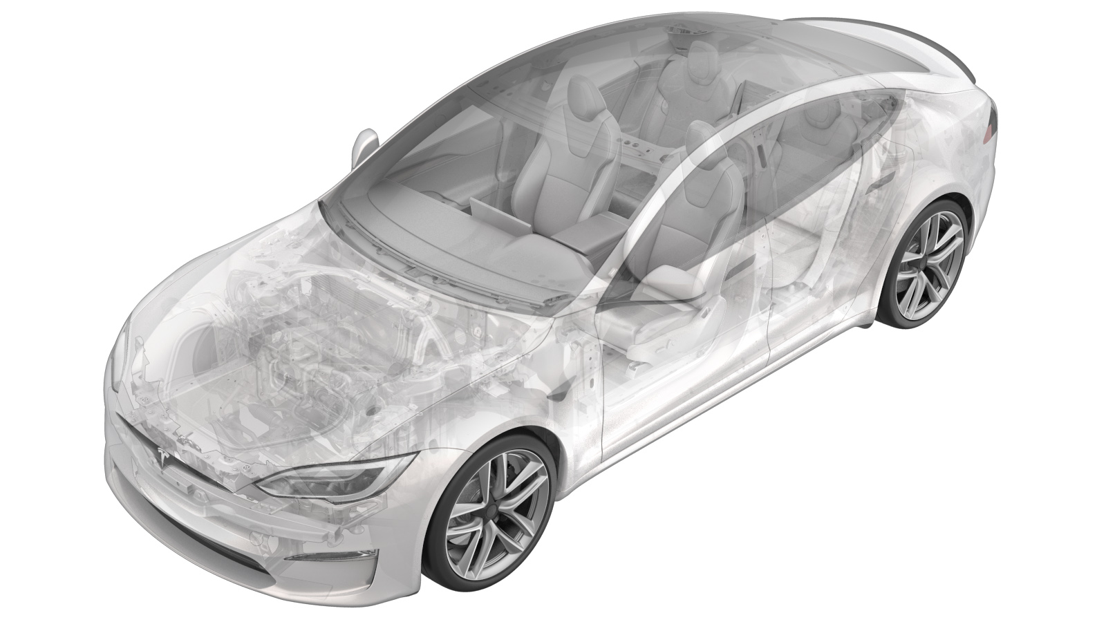
Electromechanical Brake Booster Assembly (Remove and Replace)
 Correction code
33201002
1.68
NOTE: Unless otherwise explicitly
stated in the procedure, the above correction code and FRT reflect all of the work
required to perform this procedure, including the linked procedures. Do not stack correction codes unless
explicitly told to do so.
NOTE: See Flat Rate Times to learn
more about FRTs and how they are created. To provide feedback on FRT values, email ServiceManualFeedback@tesla.com.
NOTE: See Personal Protection to make sure proper PPE is worn when
performing the below
procedure.
Remove
- Raise and support the vehicle. See Raise Vehicle - 2 Post Lift.
- Remove all four wheels. See Wheel Assembly (Remove and Install).
- Remove the rear underhood apron. See Underhood Apron - Rear (Remove and Replace).
- Disconnect LV power. See LV Power (Disconnect and Connect).
- Remove the LH footwell cover. See Cover - Footwell - Driver (Remove and Replace).
- Remove the LH knee air bag. See Knee Airbag - Driver (Remove and Replace).
-
Remove the driver floor jumper air
duct.
-
Remove the cotter clip from the clevis
pin on the pedal assembly, and remove the clevis pin from the brake pedal
assembly.
- Remove the LH and RH underhood aprons. See Underhood Apron - LH (Remove and Replace).
- Remove the LH and RH wiper arms. See Wiper Arm - LH (Remove and Replace).
- Remove the LH and RH shock tower covers. See .
- Remove the wiper cowl screen panel. See .
- Remove the LH V-brace. See V Brace - Shock Tower - LH (Remove and Replace).
- Extract brake fluid from the master cylinder reservoir and reinstall the cap.
-
Disconnect the electrical connector
from the brake booster ECU.
NoteRelease the red locking tab, then depress the black tab and rotate the lever to release.
-
Disconnect the electrical connector
from the DTS position sensor.
NoteRelease the red locking tab.
- Place shop rags beneath the brake lines to catch any fluid lost.
-
Disconnect the electrical connector
from the brake fluid level sensor.
-
Disconnect the brake lines from the
master cylinder.
-
Remove the nuts (x2) that attach the
brake booster assembly to the vehicle.
- Remove the brake booster assembly from the vehicle, maneuvering the brake lines for clearance as needed.
Install
- Install the brake booster assembly to the vehicle, maneuvering the brake lines for clearance as needed.
-
Install new nyloc nuts that attach the
brake booster assembly to the vehicle.
Note13mm, 16.5 Nm
-
Remove the protective caps from the
master cylinder brake line ports and install the brake lines to the master
cylinder.
Note12mm, 16 NmTIpClean the threads of the brake lines with brake cleaner before mating.
-
Connect the electrical connector to
the brake fluid level sensor.
- Remove the shop rags from beneath the brake lines. Clean up any residual fluid lost.
-
Connect the electrical connector to
the DTS position sensor on the brake booster.
-
Connect the brake booster ECU
connector.
NotePosition the connector and rotate the lever to fully seat, then insert the red locking tab.
- Install the LH V-brace. See V Brace - Shock Tower - LH (Remove and Replace).
- Install the wiper cowl screen panel. See .
- Install the LH and RH shock tower covers. See .
- Install the LH and RH wiper arms. See Wiper Arm - LH (Remove and Replace).
-
Align brake pedal to the brake booster
rod and install the clevis pin and clip to the brake pedal assembly.
-
Install the driver floor jumper air
duct.
- Install the LH knee air bag. See Knee Airbag - Driver (Remove and Replace).
- Install the LH footwell cover. See Cover - Footwell - Driver (Remove and Replace).
- Connect LV power. See LV Power (Disconnect and Connect).
- Connect to the vehicle using a laptop equipped with Toolbox. See Toolbox (Connect and Disconnect).
- Perform a firmware redeploy. See Firmware Reinstall - Toolbox.
- Perform a brake fluid flush. See Brake Fluid Bleed/Flush (Remove and Replace).
- Install the LH and RH underhood aprons. See Underhood Apron - LH (Remove and Replace).
- Install the rear underhood apron. See Underhood Apron - Rear (Remove and Replace).
- Install all four wheels. See Wheel Assembly (Remove and Install).
- Perform a vehicle road test using a series of ABS-active stops and make sure proper brake pedal feel and performance is achieved.