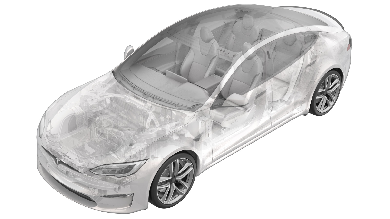
Hose - Inlet - Inverter - Rear Drive Unit (Plaid) (Remove and Replace)
 Correction code
18301712
3.12
NOTE: Unless otherwise explicitly
stated in the procedure, the above correction code and FRT reflect all of the work
required to perform this procedure, including the linked procedures. Do not stack correction codes unless
explicitly told to do so.
NOTE: See Flat Rate Times to learn
more about FRTs and how they are created. To provide feedback on FRT values, email ServiceManualFeedback@tesla.com.
NOTE: See Personal Protection to make sure proper PPE is worn when
performing the below
procedure.
Remove
- Move the vehicle to a 2 post lift. See Raise Vehicle - 2 Post Lift.
- Connect a laptop with Toolbox to the vehicle. See Toolbox (Connect and Disconnect).
- Peform a thermal fluid fill/drain. See Thermal Fluid - Cooling System (Fill/Drain).
- Release the electronic parking brake. See Park Brake Caliper - Release.
- Disconnect the laptop with Toolbox from the vehicle. See Toolbox (Connect and Disconnect).
- Remove the rear underhood apron. See Underhood Apron - Rear (Remove and Replace).
- Disconnect LV power. See LV Power (Disconnect and Connect).
-
Set the high voltage multimeter to DC
voltage, lightly touch the probes to the auxiliary battery connector contacts, and
verify that the multimeter displays a voltage.
NoteBattery voltage is typically 14.5 to 15.5 volts.
- Remove the rear wheels. See Wheel Assembly (Remove and Install).
- Remove the mid aero shield panel. See Panel - Aero Shield - Rear (Remove and Replace).
- Perform Vehicle HV Disablement Procedure. See Vehicle HV Disablement Procedure.
-
Remove the leather glove protectors
and HV insulating gloves.
- Remove the rear fascia diffuser. SeeDiffuser - Rear Fascia (Remove and Replace).
- Remove the LH and RH rear wheel arch liners. See Wheel Arch Liner - Rear - LH (Remove and Replace).
- Remove the rear subframe assembly. See Subframe Assembly - Rear (Plaid) (Remove and Install).
-
Move a coolant catcher to under the
subframe fixture assembly.
-
Release the clips (x2), disconnect the
rear drive unit inverter inlet hose from the LH and RH inverters, and then immediately
plug the fittings.
-
Release the clips (x9) that attach the
rear drive unit inverter inlet hose to the rear subframe, and then remove the hose from
the front of the subframe.
Install
-
Install the rear drive unit inverter
inlet hose to the rear subframe, and then fasten the clips (x9) that attach the hose to
the subframe.
-
Remove the plugs from the fittings,
immediately connect the rear drive unit inverter inlet hose to the LH and RH inverters,
fasten the clips (x2) and then performa a Push-Pull-Push check of the fittings.
-
Remove the coolant catcher from under
the subframe fixture assembly.
- Install the rear subframe assembly. See Subframe Assembly - Rear (Plaid) (Remove and Install).
- Install the LH and RH rear wheel arch liners. See Wheel Arch Liner - Rear - LH (Remove and Replace).
- Install the rear fascia diffuser. SeeDiffuser - Rear Fascia (Remove and Replace).
- Install the mid aero shield panel. See Panel - Aero Shield - Rear (Remove and Replace).
- Install the rear wheels. See Wheel Assembly (Remove and Install).
- Perform a cooling system vacuum refill. See Cooling System (Vacuum Refill).
- Connect LV power. See LV Power (Disconnect and Connect).
- Engage the electronic parking brake. See Park Brake Caliper - Release.
- Connect a laptop with Toolbox to the vehicle. See Toolbox (Connect and Disconnect).
- Perform a cooling system air purge. See Cooling System (Partial Refill and Bleed).
- Disconnect the laptop with Toolbox from the vehicle. See Toolbox (Connect and Disconnect).
- Install the rear underhood apron. See Underhood Apron - Rear (Remove and Replace).
- Remove the vehicle from the 2 post lift. See Raise Vehicle - 2 Post Lift.
- Perform a four wheel alignment check, and adjust if necessary. See Four Wheel Alignment Check.