Door Assembly - Charge Port (Global) (Remove and Replace)
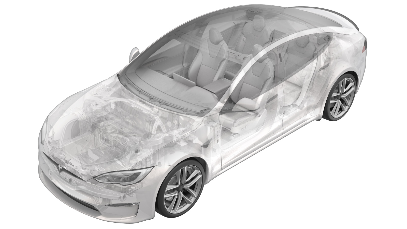 Correction code
44011512
FRT
0.78
NOTE: Unless
otherwise explicitly stated in the procedure, the correction code and its
associated FRT reflect all of the work required to perform this procedure,
including the linked procedures. Do not stack correction
codes unless explicitly told to do so.
NOTE: See Flat Rate Times to
learn more about FRTs and how they are created.
NOTE: See Personal Protection to make
sure you are wearing proper PPE when performing the procedure below.
NOTE: See Ergonomic Precautions for safe and healthy
working practices.
Correction code
44011512
FRT
0.78
NOTE: Unless
otherwise explicitly stated in the procedure, the correction code and its
associated FRT reflect all of the work required to perform this procedure,
including the linked procedures. Do not stack correction
codes unless explicitly told to do so.
NOTE: See Flat Rate Times to
learn more about FRTs and how they are created.
NOTE: See Personal Protection to make
sure you are wearing proper PPE when performing the procedure below.
NOTE: See Ergonomic Precautions for safe and healthy
working practices.
- 2026-09-21: Added checks for charge port door operation and alignment.
- 2024-04-04: Added the installation step of the busbar to the charge port nuts.
- 2023-07-06: Cleaned up procedure.
Only
technicians who have been trained in High Voltage Awareness and
have completed all required certification courses (if applicable) are permitted to
perform this procedure. Proper personal protective equipment
(PPE) and insulating HV gloves with a minimum rating
of class 0 (1000V) must be worn at all times a high voltage
cable, busbar, or fitting is handled. Refer to Tech Note
TN-15-92-003, High Voltage Awareness Care Points
for
additional glove and safety
information.
Remove
- Open the LH front door and lower the LH front window.
- Open the LH rear door and lower the LH rear window.
-
Fold the LH 2nd row 60 seat
down.
NoteSeat can be folded from the backrest button or trunk switch.NoteSince the seat cushion is not present, protect the seat as required.
- Open the liftgate.
- Remove the rear trunk parcel shelf. See Parcel Shelf - Rear Trunk (Remove and Replace).
- Remove the rear trunk load floor. See Trunk Load Floor - Rear (Remove and Replace).
- Remove the side trunk load floor. See Trunk Load Floor - Side (Remove and Replace).
- Remove the trunk sill trim. See Trim - Sill - Trunk (Remove and Replace).
- Open the charge port door using the vehicle touchscreen.
- Open the hood.
- Remove the rear underhood apron. See Underhood Apron - Rear (Remove and Replace).
- Disconnect LV power. See LV Power (Disconnect and Connect).
- Perform the charge port voltage check. See Charge Port Voltage Check.
- Remove the rear wall rear trunk trim. See Trim - Rear Trunk - Rear Wall (Remove and Replace).
- Remove the LH trunk load floor bracket. See Bracket - Trunk Load Floor - LH (Remove and Replace).
- Remove the trunk floor front trim. See Trim - Front - Floor - Trunk (Remove and Replace).
- Remove the LH 2nd row seat outer bolster. See Bolster - Outer - Seat - 2nd Row - LH (Remove and Replace).
-
Release the LH upper C-pillar trim,
and then set it aside. See Trim - C-Pillar - Upper - LH (Remove and Replace).
NoteDo not remove the lower bolt that attaches the LH 2nd row seat belt retractor.
- Remove the LH trunk side trim. See Trim - Side - Trunk - LH (Remove and Replace).
- Remove the LH taillight. See Taillight - LH (Global) (Remove and Replace).
-
Disconnect the charge port latch
electrical connector.
NoteTake note of harness routing.NotePull the red locking tab outwards to release the lock, and then pull again to release the electrical connector.
-
Disconnect the charge port electrical
connector.
NoteCarefully remove the white locking tab. Press the tab to release the electrical connector from the charge port. Continue to pull off the connector. The connector is intended to disengage the safety cap when released.
- Remove the charge port to HV battery busbar safety cap. See Safety Cap - Busbar - Charge Port to HV Battery (Global) (Remove and Replace).
-
Remove the nuts (x2) that attach the
charge port busbars to the charge port, and then remove the busbar leads from the
studs.
 9 Nm (6.6 lbs-ft)TipUse of the following tool(s) is recommended:
- 11 mm socket
NoteNuts have captured washers.NoteTake caution of any tension present with the busbars. - Remove the charge port. See Charge Port - Global (NACS) (Remove and Replace).
-
Disconnect the charge port door
connection from the charge port ECU.
NoteTake note of the original harness routing.
-
Release the charge port door harness
grommet from the body.
NoteRelease the grommet and feed harness out.
-
Remove the bolt that attaches the
charge port door to the body.1 Nm (.7 lbs-ft)TipUse of the following tool(s) is recommended:
- 8 mm deep socket
-
Remove the charge port door assembly
from the vehicle.
Notex3 datumsNoteRelease the single datum from vehicle body. Maneuver the charge port door assembly and motor out from the rear of vehicle and guide the harness out.
Install
-
Install the charge port door assembly
to the vehicle.
Notex3 datumsNoteGuide the harness in, then maneuver the charge port door assembly and motor in from the rear of vehicle. Secure the single datum onto the body.
-
Install the bolt that attaches the
charge port door to the body.1 Nm (.7 lbs-ft)TipUse of the following tool(s) is recommended:
- 8 mm deep socket
-
Fully secure the charge port door
harness grommet onto the body.
-
Connect the charge port door
electrical connector onto the charge port ECU.
-
Install the charge port assembly into
the vehicle and attach bolts (x4).7 Nm (5.2 lbs-ft)TipUse of the following tool(s) is recommended:
- 10 mm socket
Notex2 datums.NoteStart by lining up the datums on the charge port with the charge port door, and then proceed to thread in all bolts.NoteNew charge port will come pre-applied with Penetrox. -
Secure the charge port manual release
cable onto the body.
-
Verify that the charge port studs (x2) are tightened to specification.2 Nm (1.5 lbs-ft)TipUse of the following tool(s) is recommended:
- Torx T10 bit
-
Clean the charge port assembly busbar contact surface of residual Penetrox with an
IPA wipe.
NoteUse a plastic trim tool to push the IPA wipe down between plastic divider.NoteAllow 1 minute dry time after removing the Penetrox.
-
Clean the charge port busbar contact
surface of residual Penetrox.
NoteAllow 1 minute dry time.
-
Apply Penetrox to the backside of the
busbar leads.
NoteApply 2 drops of Penetrox A-13 about 5 mm in diameter to either side of the hole on both leads. Spread evenly to verify the contact surface is fully covered.
-
Install the nuts (x2) that attach the charge port busbars to the charge port.9 Nm (6.6 lbs-ft)TipUse of the following tool(s) is recommended:
- 11 mm socket
NoteNuts have captured washers.NoteIf excessive force is required to seat the busbars, they may have been bent. Inspect for damage and replace if necessary. -
Inspect HV insulating gloves.
NoteCheck gloves for damage prior to use. Refer to service document TN-15-92-003 for information on inspecting HV gloves: https://service.tesla.com/user/documents?searchText=TN-15-92-003
-
Put on the HV insulating gloves and
leather over gloves.
-
Perform a Hioki resistance test at
each HV joint from the HV busbar lead to the charge port stud (x2 HV joints).
NoteWhen using the Hioki tester, verify that the meter has been properly adjusted and set prior to usage.NoteThe acceptable resistance is between 0.050 mΩ (50 μΩ) and 0.270 mΩ (270 μΩ).
- If the resistance is greater than 0.270 mΩ (270 μΩ), there is too much resistance in the High Voltage joint. Remove the fastener, clean areas with isopropyl alcohol, install fastener back and test again.
- If the resistance is lower than 0.050 mΩ (50 μΩ), reposition the probes and measure again.
- If the resistance is repeatedly between 0.00 mΩ and 0.050 mΩ (50 μΩ), the Hioki resistance test passed. Proceed to next step.
- Remove the leather glove protectors and HV insulating gloves.
- Install the busbar safety cap. See Safety Cap - Busbar - Charge Port to HV Battery (Global) (Remove and Replace).
-
Connect the charge port electrical
connector.
NoteFully engage the electrical connector and white locking tab. The connector is intended to lock the safety cap in place.
-
Connect the charge port latch
electrical connector.
NoteReturn the harness to its original routing: Harness sits in front of the busbars.NoteFully engage the connector and red locking tab.
- Install the LH taillight. See Taillight - LH (Global) (Remove and Replace).
- Install the LH trunk side trim. See Trim - Side - Trunk - LH (Remove and Replace).
- Install the LH upper C-pillar trim. See Trim - C-Pillar - Upper - LH (Remove and Replace).
- Install the LH 2nd row seat outer bolster. See Bolster - Outer - Seat - 2nd Row - LH (Remove and Replace).
- Install the trunk floor front trim. See Trim - Front - Floor - Trunk (Remove and Replace).
- Install the LH trunk load floor bracket. See Bracket - Trunk Load Floor - LH (Remove and Replace).
- Install the rear wall rear trunk trim. See Trim - Rear Trunk - Rear Wall (Remove and Replace).
- Install the trunk sill trim. See Trim - Sill - Trunk (Remove and Replace).
- Install the side trunk load floor. See Trunk Load Floor - Side (Remove and Replace).
- Install the rear trunk load floor. See Trunk Load Floor - Rear (Remove and Replace).
- Install the rear trunk parcel shelf. See Parcel Shelf - Rear Trunk (Remove and Replace).
- Close the liftgate.
-
Restore the LH 2nd row 60 seat into upright position.
NoteRemove seat cushion protection.
- Raise the LH rear window and the LH rear door.
- Reconnect LV power. See LV Power (Disconnect and Connect).
-
Check the charge port door for correct operation and alignment.
- Open and close the charge port door from the touchscreeen
- Confirm that the charge port door opens fully, closes fully, and does not bind or contact the body or tail light
- With the door closed, check gap and flush to the body and taillight. If gap or flush is out of specification, adjust the charge port door. See Door - Charge Port (Global) (Adjust)
- Install the rear underhood apron. See Underhood Apron - Rear (Remove and Replace).
- Close the hood.
-
Verify operation of the vehicle
charging system.
-
Close the charge port door.
- Raise the LH front window and close the LH front door.