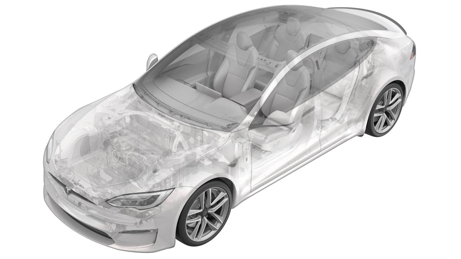
Car Computer (HW3) (Remove and Install)
 Correction code
21151001
0.60
NOTE: Unless otherwise explicitly
stated in the procedure, the above correction code and FRT reflect all of the work
required to perform this procedure, including the linked procedures. Do not stack correction codes unless
explicitly told to do so.
NOTE: See Flat Rate Times to learn
more about FRTs and how they are created. To provide feedback on FRT values, email ServiceManualFeedback@tesla.com.
NOTE: See Personal Protection to make sure proper PPE is worn when
performing the below
procedure.
Remove
- Open the front doors and lower the front windows.
- Move the front seat backward.
- Remove the rear underhood apron. See Underhood Apron - Rear (Remove and Replace).
- Disconnect LV power. See LV Power (Disconnect and Connect).
- Remove the RH middle A-pillar trim. See Trim - A-Pillar - Middle - LH (Remove and Replace).
- Remove the RH lower A-pillar trim. See Trim - A-Pillar - Lower - LH (Remove and Replace).
- Remove the passenger footwell cover. See Cover - Footwell - Passenger (Remove and Replace).
- Remove the front passenger footrest panel. See Panel - Footrest - Front Passenger (LHD) (Remove and Replace).
-
Depress the connector lock on the
underside of the connector, and then disconnect the connector to the gaming MCU.
CAUTIONDo not release the connector without releasing the connector lock first. Damage to the PCBA may occur if removed without releasing the connector lock.
-
Release the connector lock, and then
disconnect the connector to the connectivity module.
NoteMove the release lock rearward before disconnecting the connector.
-
Release the connector locks, and then
disconnect the connectors (x6) at the LH side of the entertainment motherboard.
-
Release the connector locks, and then
disconnect the connectors (x7) at the LH side of the AP motherboard.
-
Release the connector locks, and then
disconnect the connectors (x6) at the RH side of the entertainment motherboard.
-
Release the connector locks, and then
disconnect the connectors (x3) at the RH side of the AP motherboard.
-
Install coolant hose clamps to the
coldplate hoses (x2).
NotePlace coolant absorbent mats or rags around the car computer.
-
Release the coolant hoses (x2) from
the car computer coldplate assembly, and then install coolant plugs on the both hoses
and car computer.
-
Remove the bolts (x2) and nut that
attach the car computer to the vehicle, and then remove the car computer from the
vehicle.
 7 Nm (5.2 lbs-ft)
 8 Nm (5.9 lbs-ft)NoteClean up any residual coolant from the vehicle.TIpUse of the following tool(s) is recommended:
- 10 mm socket
Install
-
Position the car computer into the vehicle, and then install the bolts (x2) and nut
that attach the car computer to the vehicle.
 7 Nm (5.2 lbs-ft)
 8 Nm (5.9 lbs-ft)NoteThe bolts are torqued to 7 Nm. The nut is torqued to 8 Nm.TIpUse of the following tool(s) is recommended:
- 10 mm socket
-
Place coolant absorbent mats or rages
around the car computer, remove the coolant plugs, and then secure the coolant hoses
(x2) to the car computer coldplate assembly.
NotePerform a pull-push-pull test on each hose coupling.
-
Remove the coolant hose clamps to the coldplate hoses (x2).
NotePlace coolant absorbent mats or rags around the car computer. Clean any residual fluid and inspect for leaks.
-
Connect the connectors (x3) at the RH side of the AP motherboard, and then secure the
connector locks.
-
Connect the connectors (x6) at the RH side of the entertainment motherboard, and then
secure the connector locks.
-
Connect the connectors (x7) at the LH side of the AP motherboard, and then secure the
connector locks.
-
Connect the connectors (x6) at the LH side of the entertainment motherboard, and then
secure the connector locks.
-
Connect the connector to the connectivity module, and then secure the connector
lock.
NoteSlide the lock underneath the connector.
-
Connect the connector to the gaming MCU.
NoteMake sure the connector is fully seated into the socket.
- Inspect the coolant bottle level and top off as necessary.
- Connect LV power. See LV Power (Disconnect and Connect).
- Perform a cooling system check and fill. See Cooling System (Partial Refill and Bleed).
- Install the rear underhood apron. See Underhood Apron - Rear (Remove and Replace).
- Install the front passenger footrest panel. See Panel - Footrest - Front Passenger (LHD) (Remove and Replace).
- Install the passenger footwell cover. See Cover - Footwell - Passenger (Remove and Replace).
- Install the RH middle A-pillar trim. See Trim - A-Pillar - Middle - LH (Remove and Replace).
- Install the RH lower A-pillar trim. See Trim - A-Pillar - Lower - LH (Remove and Replace).
- Install the RH center console side panel carpet. See Carpet - Side Panel - Center Console - LH (Remove and Replace).
- Install the passenger footwell cover. See Cover - Footwell - Passenger (Remove and Replace).
- Move the front passenger seat back to its original position.
- Raise the front windows and close the front doors.