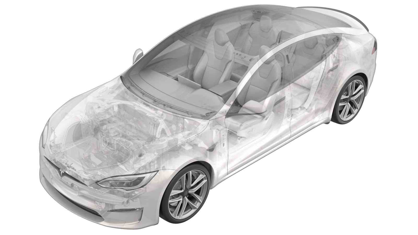
Connectivity Board - Car Computer (Remove and Replace)
 Correction code
21152902
0.42
NOTE: Unless otherwise explicitly
stated in the procedure, the above correction code and FRT reflect all of the work
required to perform this procedure, including the linked procedures. Do not stack correction codes unless
explicitly told to do so.
NOTE: See Flat Rate Times to learn
more about FRTs and how they are created. To provide feedback on FRT values, email ServiceManualFeedback@tesla.com.
NOTE: See Personal Protection to make sure proper PPE is worn when
performing the below
procedure.
Remove
- Open the RH front door.
- Lower the RH front window.
- Move the RH front seat backwards.
- Remove the rear underhood apron. See Underhood Apron - Rear (Remove and Replace).
- Disconnect LV power. See LV Power (Disconnect and Connect).
-
Remove the RH front floor mat.
- Remove the passenger footwell cover. See Cover - Footwell - Passenger (Remove and Replace).
- Remove the RH middle A-pillar trim. See Trim - A-Pillar - Middle - LH (Remove and Replace).
- Remove the RH lower A-pillar trim. See Trim - A-Pillar - Lower - LH (Remove and Replace).
-
Fold the RH front cabin carpet aside for access.
- Remove the RH center console side panel carpet. See Carpet - Side Panel - Center Console - LH (Remove and Replace).
- Remove the front passenger footrest panel. See Panel - Footrest - Front Passenger (LHD) (Remove and Replace).
-
Disconnect the car computer connectivity board connector on the LH side of the AP mother board.
NoteDisconnect the (brown) antenna connector that crosses in front of car computer cover. Release the lock on the connector before removal.TIpUse of the following tool(s) is recommended:
- Pocket screwdriver
-
Disconnect the car computer connectivity board connector.
NoteMove the release lock rearwards before removal.
-
Put on the ESD wrist strap and connect to vehicle ground.
TIpUse of the following tool(s) is recommended:
- ESD wrist strap - 1080292-00-A
-
Remove and discard the screws (x9) that attach the car computer connectivity board cover to the connectivity board, and then remove the cover from the board.
TIpUse of the following tool(s) is recommended:
- ESD wrist strap - 1080292-00-A
- Mini ratchet bit set
-
Remove and discard the screws (x6) that attach the car computer connectivity board to the vehicle.
TIpUse of the following tool(s) is recommended:
- ESD wrist strap - 1080292-00-A
- Mini ratchet bit set
-
Carefully slide the car computer connectivity board downwards to disconnect the PCB connector, and then remove the connectivity board from the vehicle.
NoteEnsure full disengagement of the connectivity board before attempting to remove.TIpUse of the following tool(s) is recommended:
- ESD wrist strap - 1080292-00-A
Install
-
Position the car computer connectivity board on the vehicle, and then carefully slide the connectivity board upwards to connect the PCB connector.
NoteAlign the datum with the slot in the connectivity card and fully engage.TIpUse of the following tool(s) is recommended:
- ESD wrist strap - 1080292-00-A
-
Install the new screws (x6) that attach the car computer connectivity board to the vehicle.
 0.7 Nm (6 lbs-in)TIpUse of the following tool(s) is recommended:
- T10 blade attachment
- ESD wrist strap - 1080292-00-A
- Mini ratchet bit set
- Wiha torque setter
- Wiha torqueVario-S 0.10Nm - 0.6Nm
-
Position the car computer connectivity board cover on the connectivity board, and then install the new screws (x9) that attach the cover to the board.
 1.4 Nm (1.0 lbs-ft)TIpUse of the following tool(s) is recommended:
- ESD wrist strap - 1080292-00-A
- Mini ratchet bit set
- Ratchet/torque wrench
-
Remove the ESD wrist strap.
TIpUse of the following tool(s) is recommended:
- ESD wrist strap - 1080292-00-A
-
Connect the car computer connectivity board connector.
NoteEngage the release lock underneath the connector.
-
Connect the car computer connectivity board connector on the LH side of the AP mother board.
- Install the front passenger footrest panel. See Panel - Footrest - Front Passenger (LHD) (Remove and Replace).
-
Fold the RH front cabin carpet into original position.
- Install the RH middle A-pillar trim. See Trim - A-Pillar - Middle - LH (Remove and Replace).
- Install the RH lower A-pillar trim. See Trim - A-Pillar - Lower - LH (Remove and Replace).
- Install the RH center console side panel carpet. See Carpet - Side Panel - Center Console - LH (Remove and Replace).
- Install the passenger footwell cover. See Cover - Footwell - Passenger (Remove and Replace).
-
Install the RH front floor mat.
- Connect LV power. See LV Power (Disconnect and Connect).
- Install the rear underhood apron. See Underhood Apron - Rear (Remove and Replace).
- Move the RH front seat into original position.
-
Verify BT, WiFi, and LTE are functioning properly.
- Raise the RH front window.
- Close the RH front door.