Brake Lines - Left Brake Tube Pipe Assembly (Remove and Install)
 Correction code
3303019031
3303019032
FRT
1.02
NOTE: Unless
otherwise explicitly stated in the procedure, the above correction code and
FRT reflect all of the work required to perform this procedure, including
the linked procedures. Do
not stack correction codes unless explicitly told to do so.
NOTE: See Flat Rate Times to learn more about FRTs and how they are
created. To provide feedback on FRT values, email LaborTimeFeedback@tesla.com.
NOTE: See Personal Protection to make
sure wearing proper PPE when performing the below procedure.
Correction code
3303019031
3303019032
FRT
1.02
NOTE: Unless
otherwise explicitly stated in the procedure, the above correction code and
FRT reflect all of the work required to perform this procedure, including
the linked procedures. Do
not stack correction codes unless explicitly told to do so.
NOTE: See Flat Rate Times to learn more about FRTs and how they are
created. To provide feedback on FRT values, email LaborTimeFeedback@tesla.com.
NOTE: See Personal Protection to make
sure wearing proper PPE when performing the below procedure.
Remove
- Open the LH front door and lower the LH front window.
- Raise and support the vehicle. See Raise Vehicle - 2 Post Lift.
- Remove the rear underhood apron. See Underhood Trim - Rear Apron Assembly (Remove and Install).
- Remove the frunk assembly. See Frunk Assembly (Remove and Install).
- Place the vehicle into Service Mode. See Service Mode.
- Unlock the vehicle Gateway. See Gateway (Unlock).
- On the vehicle touchscreen, navigate to Service Mode > Thermal > Refrigerant System.
-
Touch Start Thermal Fill Drain (Coolant and
Refrigerant) and allow the routine to complete.
NoteAllow the routine to complete. Make sure the routine is successful.
- Disconnect MV power. See Disconnect MV Power.
- Remove all 4 wheels. See Wheel Assembly (Remove and Install).
- Remove the LH front fender flare cover. See Front and Rear Garnish - Carrier - Front Fender Flare Aft - LH (Remove and Install).
- Remove the LH front wheel liner. See Wheel Arch Liners - Front Wheel Liner - LH (Remove and Replace).
-
Position an oil drain container
underneath the LH front brake pipe.

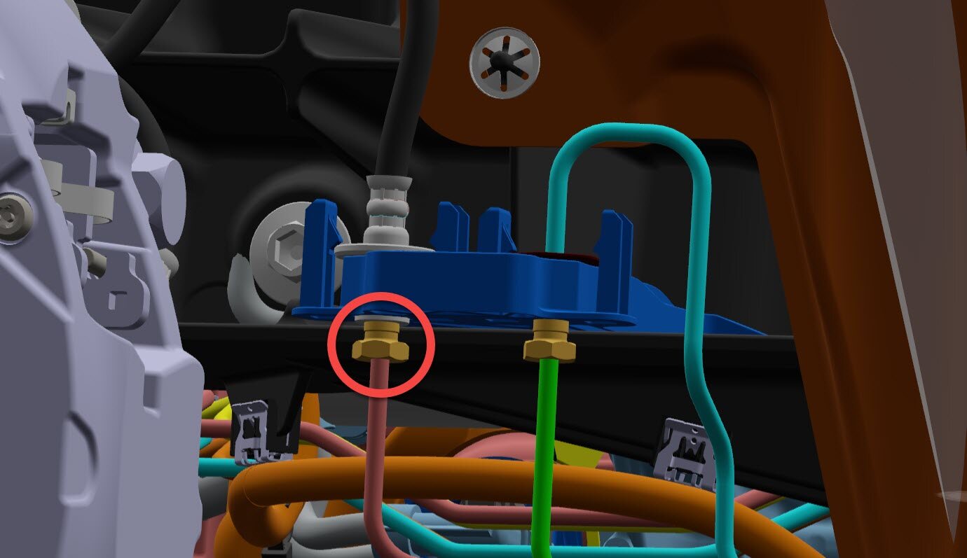
-
Release the nut that attaches the LH
front brake tube to the LH front brake hose, and then release the tube from the brake
hose.
 16 Nm (11.8 lbs-ft)Tip: Use of the following tool(s) is recommended:
- 12 mm socket
- Remove the oil drain container from the underneath vehicle.
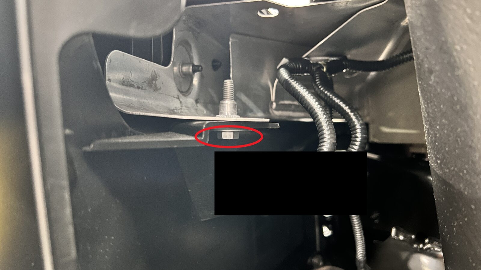
-
Remove the bolt that attaches the LH
side of the fascia to the vehicle.6 Nm (4.4 lbs-ft)NotePull the wheel liner back for access.Tip: Use of the following tool(s) is recommended:
- 10 mm socket
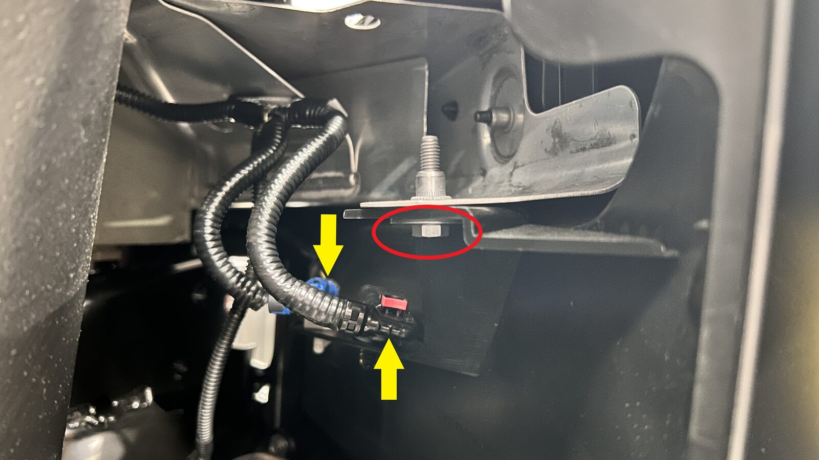
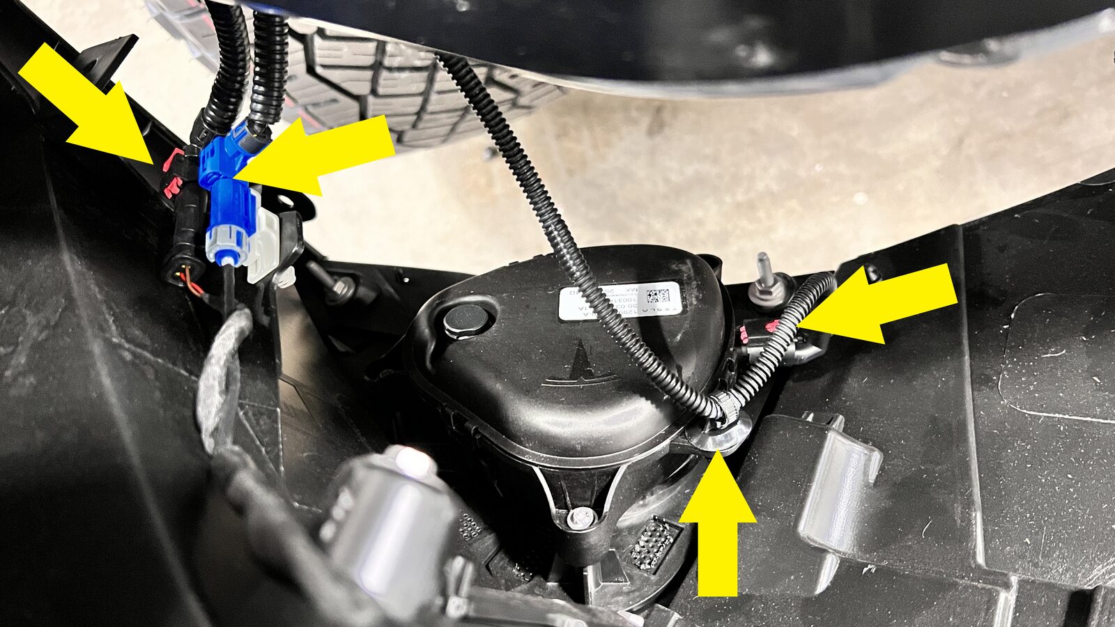
-
Release the connector lock and
disconnect the electrical connectors (x3), release the harness clip, and then remove the
bolt that attaches the RH side of the fascia to the vehicle.6 Nm (4.4 lbs-ft)CAUTIONDo not push down on the locking tab.NotePull the wheel liner back for access.Tip: Use of the following tool(s) is recommended:
- 10 mm socket
- Raise the vehicle fully.
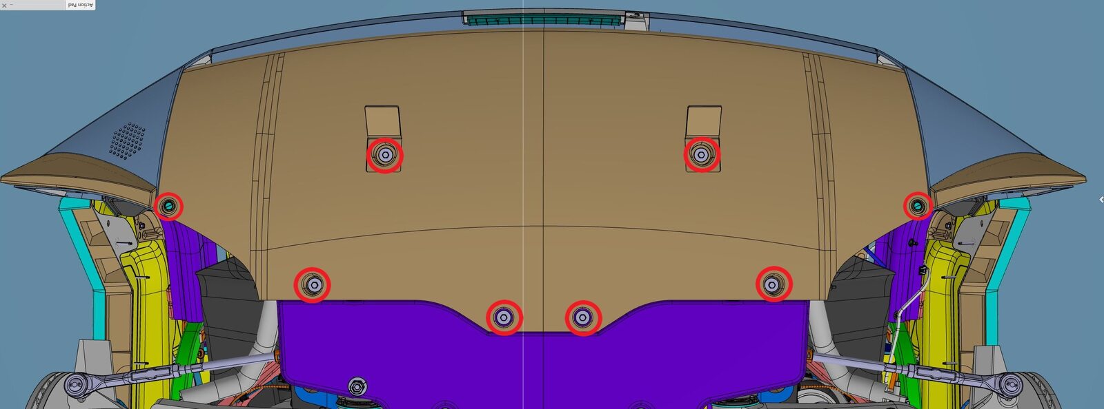
-
Remove the bolts (x6) and release the
clips (x2) that attach the lower valance to the body, and then remove the valance from
the vehicle.6 Nm (4.4 lbs-ft)NoteRelease the covers to expose the bolts.Tip: Use of the following tool(s) is recommended:
- 10 mm socket
Figure 1. LH shown; RH similar 
Figure 2. LH shown; RH similar 
- Remove the front aeroshield. See Undertray - Front Aeroshield (Remove and Install).
-
Disconnect the Cooling Fan Module
(CFM) electrical connectors (x2).
Figure 3. LH shown; RH similar 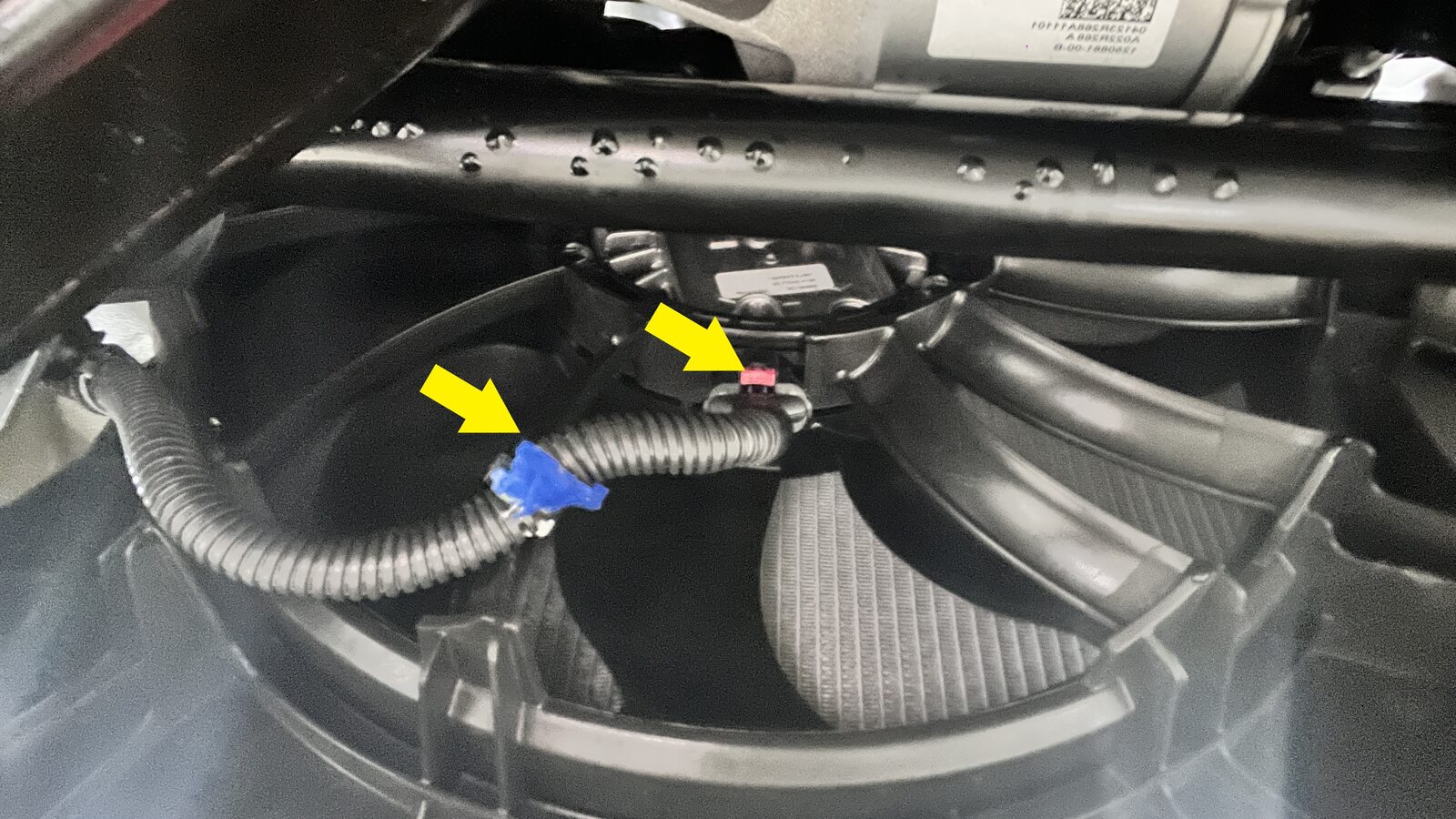
- Lower the vehicle fully.
- Remove the front center applique. See Front Grille and Applique - Front Center Applique Assembly (Remove and Install).
- Remove the front fascia. See Front Bumper Fascia - Front Fascia (Remove and Install).
- Remove the cooling fan module. See Fan and Radiator - Cooling Fan Module (Remove and Install).
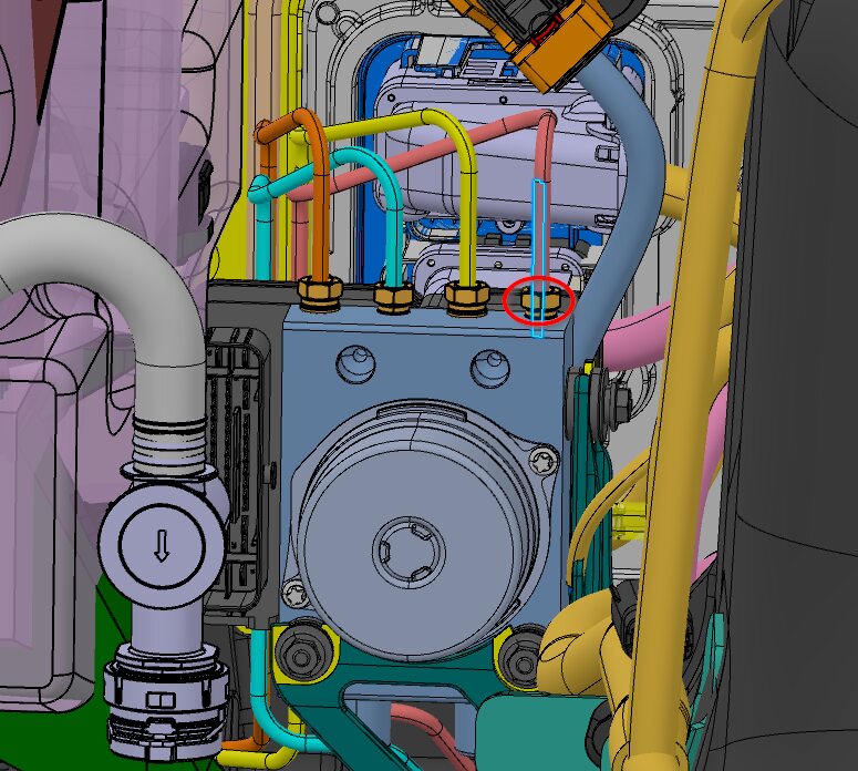
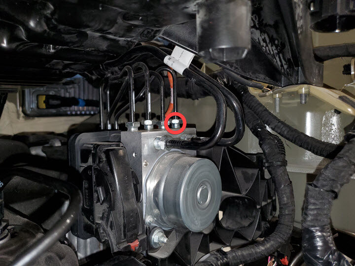
-
Release the nut that attaches the LH
front brake line tube to the hydraulic control unit, and then remove the tube from the
vehicle.16 Nm (11.8 lbs-ft)Tip: Use of the following tool(s) is recommended:
- 14 mm combination wrench
Install
-
Install the LH front brake line tube
into the hydraulic control unit, and then hand tighten the nut that attaches the tube to
the assembly.
Tip: Use of the following tool(s) is recommended:
- 14 mm combination wrench
-
Torque the LH front brake line tube nut.16 Nm (11.8 lbs-ft)Tip: Use of the following tool(s) is recommended:
- 14 mm combination wrench
- Install the cooling fan module. See Fan and Radiator - Cooling Fan Module (Remove and Install).
- Install the front fascia. See Front Bumper Fascia - Front Fascia (Remove and Install).
- Position the oil drain container underneath the LH front brake pipe.
-
Install the LH front brake tube into the LH front brake hose, and then install the
nut that attaches the tube to the brake hose.16 Nm (11.8 lbs-ft)Tip: Use of the following tool(s) is recommended:
- 12 mm socket
- Remove the oil drain from underneath the vehicle.
- Install the LH front wheel liner. See Wheel Arch Liners - Front Wheel Liner - LH (Remove and Replace).
- Install the LH front fender flare cover. See Front and Rear Garnish - Carrier - Front Fender Flare Aft - LH (Remove and Install).
- Install the front aeroshield. See Undertray - Front Aeroshield (Remove and Install).
-
Position the lower valance onto the
vehicle, and then install the bolts (x6) that attach the valance to the vehicle.6 Nm (4.4 lbs-ft)Tip: Use of the following tool(s) is recommended:
- 10 mm socket
Figure 4. LH shown; RH similar 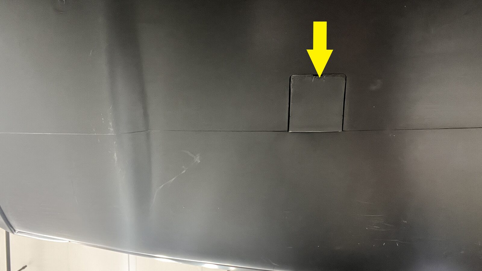
Figure 5. LH shown; RH similar 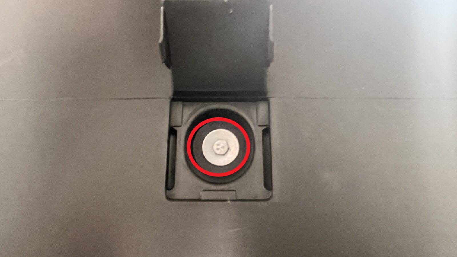

- Lower the vehicle to access the frunk area.
- Reconnect MV power. See Disconnect MV Power.
-
On the vehicle touchscreen, navigate
to Thermal > Actions > Test Thermal Performance, tap
Run, and allow the routine to complete.
NoteIf the thermal test fails, follow Toolbox article 206000.
- Bleed all 4 brakes. See Brake Fluid Bleed - One Caliper.
- Install the rear underhood apron. See Underhood Trim - Rear Apron Assembly (Remove and Install).
- Install all 4 wheels. See Wheel Assembly (Remove and Install).
- Remove the vehicle from the lift. See Raise Vehicle - 2 Post Lift.
- Raise the LH front window and close the LH front door.