2024-01-11
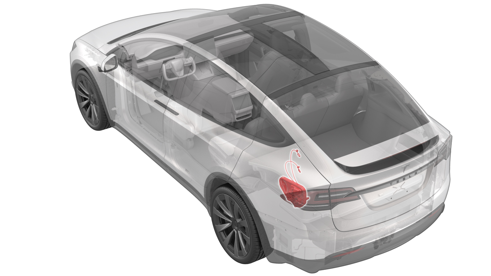
Charge Port (GB/T Charging Standard) (Remove and Replace)
 Correction code
44012702
1.50
NOTE: Unless otherwise explicitly
stated in the procedure, the above correction code and FRT reflect all of the work
required to perform this procedure, including the linked procedures. Do not stack correction codes unless
explicitly told to do so.
NOTE: See Flat Rate Times to learn
more about FRTs and how they are
created.
NOTE: See Personal Protection to make sure proper PPE is worn when
performing the below
procedure.
Correction code
44012702
1.50
NOTE: Unless otherwise explicitly
stated in the procedure, the above correction code and FRT reflect all of the work
required to perform this procedure, including the linked procedures. Do not stack correction codes unless
explicitly told to do so.
NOTE: See Flat Rate Times to learn
more about FRTs and how they are
created.
NOTE: See Personal Protection to make sure proper PPE is worn when
performing the below
procedure.
Equipment:
- 1076927-00-A Hioki tester
- 1076928-00-A Test Probes - Hioki 9461
| Description | Torque Value | Recommended Tools | Reuse/Replace | Notes |
|---|---|---|---|---|
| Nuts (x2) that attach the charge port busbar to the charge port |
 9 Nm (6.6 lbs-ft) |
|
Reuse | |
| Bolts (x4) that secure the charge port assembly |
7 Nm (5.2 lbs-ft) |
|
Reuse |
Remove
- Open the LH front door and lower the LH front window.
- Move the LH front seat forward.
- Open the LH falcon wing door, and move the LH monopost seat forward.
- Remove the rear sill panel trim. See Trim - Sill Panel - Rear - LH (Remove and Replace).
- On the touchscreen, tap to open the charge port.
- Remove the rear underhood apron. See Underhood Apron - Rear (Remove and Replace).
- Remove the rear trunk crush can trim. See Trim - Crush Can - Rear Trunk - LH (Remove and Replace).
-
Release the clip that attaches the LH soft trim pocket bracket to the vehicle, and
remove the bracket.
- Remove the LH upper C-pillar trim. See Trim - C-Pillar - Upper - LH (Remove and Replace).
- Remove the LH middle C-pillar zone bracket. See Bracket - Zone - C-Pillar - Mid - LH (6/7 Seat) (Remove and Replace).
- Remove the LH trunk trim bracket. See Bracket - Trim - Trunk - LH (Remove and Replace).
- Raise the LH 3rd row seatback into the upright position.
- Perform the charge port voltage check. See Charge Port Voltage Check.
- Remove the 3rd row seat cushion. See Cushion - Seat - 3rd Row (Remove and Replace).
- Remove the inner reinforcement. See Reinforcement - Inner - LH (Remove and Replace).
-
Remove the white locking tab and disconnect the AC logic connector from the charge
port assembly.
-
Remove the white locking tab and disconnect the DC logic connector from the charge
port assembly.
-
Disconnect the charge port actuator logic connector from the charge port
assembly.
NoteDo not push down on the red tab. Pull the red tab to disengage the lock, then pull it again to release the connector.
-
Release the tabs (x2) to remove the charge port safety cap.
-
Remove the nuts (x2) that attach the charge port busbar to the charge port, and
remove the busbar leads from the studs.
NoteThe nuts have captured the washers. Take caution of any tension present with the busbar.TIpUse of the following tool(s) is recommended:
- Flex head ratchet/flex head torque wrench
- 4 in extension
- 11 mm deep socket
- Ratchet/torque wrench
-
Release the dual-step locking tab to release the AC inlet harness electrical
connector from the charge port.
-
Remove the bolts (x4) that secure the charge port assembly, and remove the charge
port assembly from the vehicle.
NoteThe charge port is bolted to the charge port door and is lined up with 2 datums.TIpUse of the following tool(s) is recommended:
- Flex head ratchet/flex head torque wrench
- 6 in extension
- 10 mm socket
- Ratchet/torque wrench
Install
-
Line up the datums on the charge port with the charge port door, then thread in the
bolts (x4) that secure the charge port assembly.7 Nm (5.2 lbs-ft)NoteNew charge port will come pre-applied with penetrox.TIpUse of the following tool(s) is recommended:
- Flex head ratchet/flex head torque wrench
- 6 in extension
- 10 mm socket
- Ratchet/torque wrench
-
Secure the dual-step locking tab to connect the AC inlet harness electrical connector
to the charge port.
-
Apply 2 drops of Penetrox A-13 about 5mm in diameter to either side of the hole on
both busbar leads, and spread evenly to make sure the contact surface is fully
covered.
-
Install the nuts (x2) that attach the charge port busbar to the charge port.9 Nm (6.6 lbs-ft)NoteThe nuts have captured the washers. If excessive force is required to seat the busbars, they may have been bent. Inspect for damage and replace if necessary.TIpUse of the following tool(s) is recommended:
- Flex head ratchet/flex head torque wrench
- 4 in extension
- 11 mm deep socket
- Ratchet/torque wrench
-
Put on the HV insulating gloves and the leather over gloves, then perform Hioki
resistance test at each HV joint from the HV busbar lead to the charge port stud, and
then remove the gloves.
- If the resistance is greater than 0.270 mΩ (270 μΩ), stop the work and escalate the Toolbox session.
- If the resistance is lower than 0.050 mΩ (50 μΩ), reposition the probes and measure again.
- If the resistance repeats between 0.00 mΩ and 0.050 mΩ (50 μΩ), Hioki test is passed, proceed to next step.
-
Secure the tabs (x2) to install the charge port safety cap.
NoteThe safety cap will click into position.
-
Engage the locking tab to connect the charge port actuator logic connector to the
charge port assembly.
-
Secure the white locking tab to connect the DC logic connector to the charge port
assembly.
-
Secure the white locking tab to connect the AC logic connector to the charge port
assembly.
- Install the inner reinforcement. See Reinforcement - Inner - LH (Remove and Replace).
- Install the 3rd row seat cushion. See Cushion - Seat - 3rd Row (Remove and Replace).
- Connect LV power. See LV Power (Disconnect and Connect).
- Install the rear underhood apron. See Underhood Apron - Rear (Remove and Replace).
- Verify the operation of the vehicle charging system, and then close the charge port door.
- Install the LH trunk trim bracket. See Bracket - Trim - Trunk - LH (Remove and Replace).
- Install the LH middle C-pillar zone bracket. See Bracket - Zone - C-Pillar - Mid - LH (6/7 Seat) (Remove and Replace).
- Install the LH upper C-pillar trim. See Trim - C-Pillar - Upper - LH (Remove and Replace).
-
Align the datum, and secure the clip that attaches the LH soft trim pocket bracket to
the vehicle.
- Install the rear trunk crush can trim. See Trim - Crush Can - Rear Trunk - LH (Remove and Replace).
- Move the LH Monopost seat to original position.
- Install the rear sill panel trim. See Trim - Sill Panel - Rear - LH (Remove and Replace).
-
Hold the LH upper B-pillar button in the down position to manually calibrate the LH
falcon wing door, and then calibrate the RH falcon wing door in the same way.
NoteThe doors must be calibrated and closed for firmware to pass.
- Move the LH front seat to original position.
- Raise the LH front window and close the LH front door.