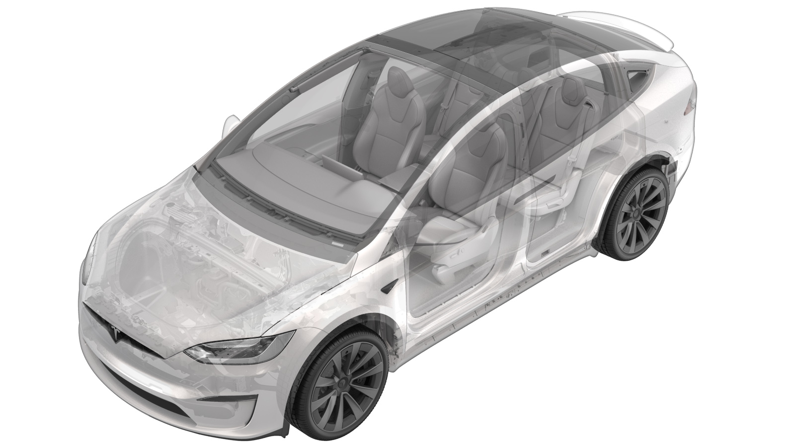
Sensor - Parking Distance - Outer - Front (HW3) (Remove and Replace)
 Correction code
17271022
0.30
NOTE: Unless otherwise explicitly
stated in the procedure, the above correction code and FRT reflect all of the work
required to perform this procedure, including the linked procedures. Do not stack correction codes unless
explicitly told to do so.
NOTE: See Flat Rate Times to learn
more about FRTs and how they are created. To provide feedback on FRT values, email ServiceManualFeedback@tesla.com.
NOTE: See Personal Protection to make sure proper PPE is worn when
performing the below
procedure.
Remove
- Open the LH front door and lower the LH front window.
- Press the brake pedal to turn on drive rails.
- Use the touchscreen to set the air suspension ride height to “Very High”.
- Use the touchscreen to set the air suspension into "Jack Mode".
- Turn the steering wheel fully to the right.
- Disconnect LV Power. See LV Power (Disconnect and Connect).
- Remove the LH front fender garnish, but do not remove the wheel fairing from the garnish. See Fender Garnish and Wheel Fairing Assembly - Front - LH (Remove and Replace).
-
If servicing sensors S2 or S5:
Release the clips (x6) and push nut that attach the front portion of the LH front wheel
arch liner to the vehicle.
- Move the liner aside for access.
-
Release the connector lock, and then
disconnect the LH front outer parking distance sensor electrical connector.
CAUTIONDO NOT push down on the red locking tab. Pull the tab away from the connector until the connector is unlocked, and then continue pulling to release the connector.
-
Release the securing tabs (x2), and
then remove the LH front outer parking distance sensor from the front fascia
assembly.
Install
-
Position the LH front outer parking distance sensor into the front fascia assembly,
and then secure the tabs (x2).
NoteVerify the sensor is seated flush against the front fascia.
-
Connect the LH front outer parking distance sensor electrical connector, and then
engage the locking tab.
CAUTIONPush the red locking tab into the connector to engage the locking mechanism. DO NOT push down or pull up on the red locking tab.
-
Move the front lower portion of the LH
front wheel arch liner into the original position.
-
If servicing sensors S2 or S5:
Install the clips (x6) and push nut that attach the front portion of the LH front
wheel arch liner to the vehicle.
- Install the LH front fender garnish. See Fender Garnish and Wheel Fairing Assembly - Front - LH (Remove and Replace).
-
Connect LV power. See LV Power (Disconnect and Connect).
NoteAfter connecting LV power, do not shift the vehicle to Drive until the Toolbox routine (further below) is performed. Failure to do so can trigger vehicle alerts.
- On the vehicle touchscreen, touch to deactivate Jack Mode.
- On the vehicle touchscreen, touch .
- Connect a laptop with Toolbox to the vehicle. See Toolbox (Connect and Disconnect).
- In Toolbox, click the Actions tab, type TEST-RESET_PARKvia Toolbox: (link) into the search field, click TEST-RESET_PARKvia Toolbox: (link), click Run, and then allow the routine to complete.
- In Toolbox, click the Actions tab, type "USS Addresses" into the search field, click PROC_USM_FRONT_PROGRAM-USS-ADDRESSESvia Toolbox: (link)via Service Mode: Driver Assist ➜ Sensors ➜ Program Front USS, click Run, and then allow the routine to complete.
- Disconnect the laptop with Toolbox from the vehicle. See Toolbox (Connect and Disconnect).