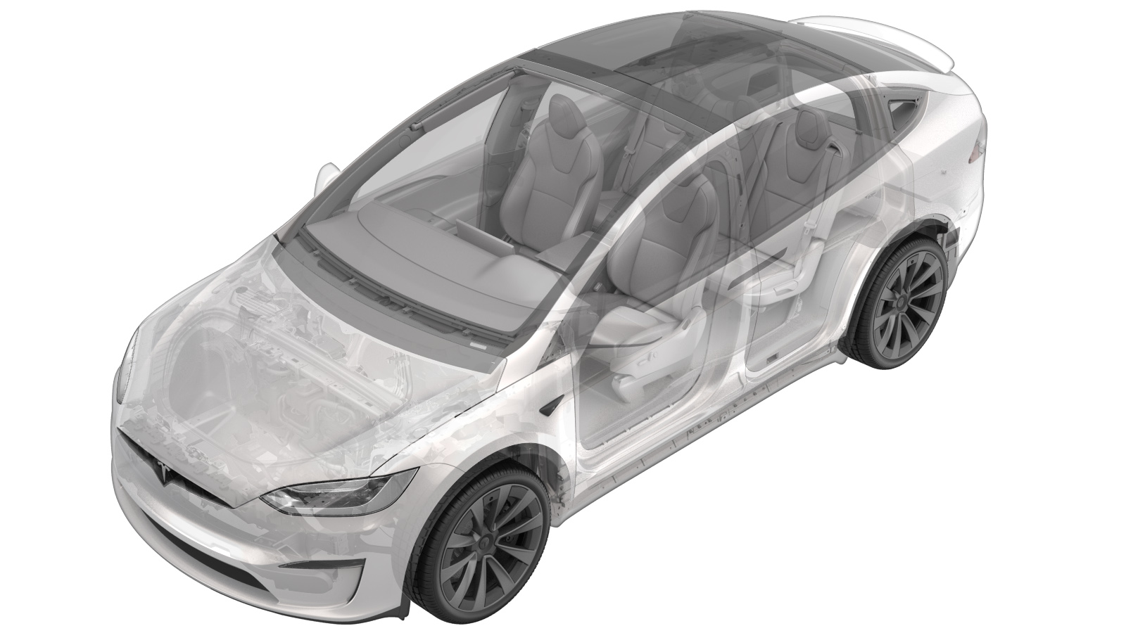
2025-11-25
Camera - Rear Facing (HW4) (Remove and Replace)
 Correction code
17222012
NOTE: Unless otherwise explicitly stated in the procedure, the above correction code and FRT reflect all of the work required to perform this procedure, including the linked procedures. Do not stack correction codes unless explicitly told to do so.
NOTE: See Flat Rate Times to learn more about FRTs and how they are created. To provide feedback on FRT values, email ServiceManualFeedback@tesla.com.
NOTE: See Personal Protection to make sure wearing proper PPE when performing the below procedure.
NOTE: See Ergonomic Precautions for safe and healthy working practices.
- 2023-06-20: Switch the steps so that DAS Reset occurs directly before the Camera Connection Test.
Warning
This procedure is a DRAFT.
Although it has been validated, Warnings and Cautions might be missing. Follow safety
requirements and use extreme caution when working on or near High Voltage systems and
components.
Remove
- Open the LH front door and lower the LH front window.
- Enable Service Mode. See Service Mode (Enable and Disable).
-
Partially open the liftgate.
NoteAllow the liftgate to open fully, and then pull the liftgate back to a comfortable working height.
-
Apply masking tape around the liftgate
applique to protect the painted surrounding area.
-
Remove the bolts (x4)
that attach the liftgate applique bracket to the liftgate.
 2 Nm (1.5 lbs-ft)TIpUse of the following tool(s) is recommended:
- TP20 bit (Mini ratchet bit set - 1450424-00-A)
-
Release the clips (x6) that attach the liftgate applique bracket to the
liftgate.
CAUTIONTake care not to damage the body of the vehicle.NoteDouble-sided tape was used on each end where the applique overlaps the liftgate taillights.
-
Disconnect the rear facing camera
electrical connector.
NotePush to lift the tab, and then disconnect the electrical connector.
-
Remove the bolts (x2) that attach the
rear facing camera to the liftgate applique bracket, and then remove the camera from the
bracket.
 0.8 Nm (7 lbs-in)TIpUse of the following tool(s) is recommended:
- TP20 bit (Mini ratchet bit set - 1450424-00-A)
Install
-
Carefully remove the old double sided
tape, clean the body surface with Isopropyl Alcohol (IPA) wipes, and then install new
double sided tape.
-
Install the bolts (x2) that attach the
rear facing camera to the liftgate applique bracket.
 0.8 Nm (7 lbs-in)TIpUse of the following tool(s) is recommended:
- TP20 bit (Mini ratchet bit set - 1450424-00-A)
-
Secure the rear facing camera
electrical connector on the liftgate applique bracket, and then connect the camera
electrical connector.
-
Reset the Driver Assistance
System (DAS).
-
HW4 cameras only: Run the camera
connection test to update the new camera's firmware.
NoteDAS Cameras are not CAN modules and cannot be updated via firmware reinstall or "Part Replacement Deploy".
- Disconnect the laptop with Toolbox from the vehicle. See Toolbox (Connect and Disconnect).
-
Install the liftgate applique
bracket.
- Peel off the new double sided tape.
- Align the tabs to the liftgate holes, and then push the bracket into position.
- Apply pressure on the applique to help with the tape and bracket mating.
-
Install the bolts (x4) that attach the liftgate applique bracket to
the liftgate.
 2 Nm (1.5 lbs-ft)TIpUse of the following tool(s) is recommended:
- TP20 bit (Mini ratchet bit set - 1450424-00-A)
- Remove all masking tape from the vehicle after 5 minutes for the applique to properly adhere to the liftgate.
- Close the liftgate.
- Exit Service Mode. See Service Mode (Enable and Disable).
- Raise the LH front window and close the LH front door.