2025-10-20
Harness - Body - LH (2025+) (Remove and Replace)
 Correction code
NEW
FRT
6.10
NOTE: Unless otherwise explicitly stated in the procedure, the correction code and FRT listed above reflect all of the work required to perform this procedure, including the linked procedures. Do not stack correction codes unless explicitly told to do so.
NOTE: See Flat Rate Times to learn more about FRTs and how they are created.
NOTE: See Personal Protection to make sure you
are wearing proper PPE when performing the procedure below.
NOTE: See Ergonomic Precautions for safe and healthy working practices.
Correction code
NEW
FRT
6.10
NOTE: Unless otherwise explicitly stated in the procedure, the correction code and FRT listed above reflect all of the work required to perform this procedure, including the linked procedures. Do not stack correction codes unless explicitly told to do so.
NOTE: See Flat Rate Times to learn more about FRTs and how they are created.
NOTE: See Personal Protection to make sure you
are wearing proper PPE when performing the procedure below.
NOTE: See Ergonomic Precautions for safe and healthy working practices.
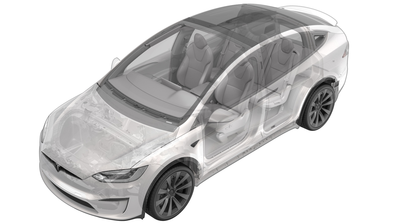
Note
This procedure describes work that is
specific to 2025+ Model X.
Remove
- Open all the 4 doors and the liftgate.
- Lower both front windows.
- Press the brake pedal to turn on drive rails.
-
On the touchscreen, tap and set the air suspension ride height to
Very High
- Place the vehicle in Service Mode by using the touchscreen. See Service Mode (Enable and Disable).
- On the touchscreen, tap to set the air suspension to Jack Mode.
- Remove the LH and RH front door sill trim panels. See Trim - Sill Panel - Front - LH (Remove and Replace).
- Remove the LH and RH front seat bolts and adjust the seat position for easy removal. See Seat Assembly - 1st Row - LH (Remove and Install).
- Remove the 2nd row rear floor board. See Floor Panel - Rear - 2nd Row (6 Seat) (Remove and Replace).
- Remove the rear trunk carpet. See Carpet - Rear Trunk (7 Seat) (Remove and Replace).
- Remove the 3rd row seat cushion. See Cushion - Seat - 3rd Row (Remove and Replace).
- Perform the charge port voltage check. See Charge Port Voltage Check.
- Remove the busbar duct assembly. See Duct - Busbar - 3rd Row - LH (Remove and Replace).
-
Remove the bolt that secures the
busbar HV connector lid.
TIpUse of the following tool(s) is recommended:
- 10 mm socket
-
Remove the bolts (x2) that attach the
HV connector to the DC FC header.
TIpUse of the following tool(s) is recommended:
- 10 mm socket
-
Remove the HV connector from the DC FC
header.
- Remove the LH and RH front seats. See Seat Assembly - 1st Row - LH (Remove and Install).
- Remove the 1st row podium. See Podium - 1st Row (Remove and Replace).
- Remove the front cabin carpet. See Carpet - 1st Row (Remove and Replace).
- Remove the 2nd row front floor panel. See Floor Panel - Front - 2nd Row (6 Seat) (Remove and Replace).
- Remove the LH B-pillar applique. See Applique - B-Pillar - LH (Remove and Replace).
- Remove the LH lower A-pillar trim. See Trim - A-Pillar - Lower - LH (Remove and Replace).
- Remove the LH upper A-pillar trim. See Trim - A-Pillar - Upper - LH (2025+) (Remove and Replace).
-
Remove the trunk sill trim (clips x4,
datums x2).
-
Remove the rear wall load support
(push clips x4, clips x2).
-
Remove the trunk tub floor
insulator.
- Remove the LH and RH upper C-pillar trims. See Trim - C-Pillar - Upper - LH (Remove and Replace).
-
Remove the LH crush can bracket (clips
x5).
-
Remove the LH soft trim pocket bracket
(clip x1, datum x1).
- Remove the LH trunk side trim. See:
-
Remove the LH trunk side bracket
(screws x3, push clips x3).
TIpUse of the following tool(s) is recommended:
- Torx T30 socket
- Remove the LH inner reinforcement. See Reinforcement - Inner - LH (Remove and Replace).
- Remove the headliner assembly. See Headliner (Remove and Replace).
-
Remove the connectors (x4) for the LH
and RH EM controllers.
-
Release the coax connector from the
center spine close out panel (tab x1) and disconnect.
-
Remove the bolts (x8) that attach the
center spine close out panel to the body.
NoteDo not allow the close out panel to hang on harness,TIpUse of the following tool(s) is recommended:
- 10 mm deep socket
-
Release the clips (x5) and remove the
center spine close out panel.
- Remove the RH footrest panel. See Panel - Footrest - Front Passenger (LHD) (Remove and Install).
- Remove the rear fascia assembly. See Fascia Assembly - Rear (Remove and Install).
-
Disconnect the LH body harness from
the trailer hitch jumper harness.
-
Disconnect the LH body harness from
the trailer hitch ECU.
-
Release the LH body harness from the
trailer hitch assembly and the body (clips x2).
- Remove the brake light switch. See Switch - Brake Light (Remove and Replace).
-
Disconnect the harness
connector.
-
Release the LH body harness from the
body controller (connectors x9).
NoteRelease the connector locks before removal.
-
Release the LH body harness from the
upper and lower A-pillar (clips x6, connectors x2).
NoteRelease the connector locks before removal. Release X940M connector from clip to prevent paint damage. Lower the fir tree clip located behind the instrument panel carrier.
-
Route the LH body harness A-pillar
branch behind the instrument panel carrier.
NoteRoute LH body harness under IP harness
-
Remove the bolt that attach the LH
body harness A-pillar branch to the footwell.
TIpUse of the following tool(s) is recommended:
- 10 mm deep socket
-
Release the LH body harness from the
pedal assembly (clips x2).
-
Release the LH body harness from the
toeboard (1x connector, 4x clips, 1x datum).
-
Release the LH body harness from the
B-pillar (3x connectors, 7x clips).
NoteDo not push down on the red tab. Pull the red tab to disengage the lock, then pull it again to release the connector. Slide both orange locking tabs simultaneously toward the rear of the connector to release the connector.
-
Release the LH body harness from the
center spine (1x bolt, 2x connectors, 4x clips).
TIpUse of the following tool(s) is recommended:
- 10 mm deep socket
-
Route the LH body harness under the
falcon door upper harness and the curtain air bag.
NoteRoute the B-pillar applique connectors through the body.
-
Release the LH body harness from the
1st row body panel (1x bolt, 5x connectors, 7x clips, 1x bracket).
NoteRelease the connector locks before removal. Release the bracket from the body studs and the hole.
-
Release the LH body harness from the
2nd row body panel (4x connectors, 3x clips).
NoteRelease the bracket for better access. Release the connector locks before removal.
-
Release the LH body harness from the
3rd row body panel (1x connector, 6x clips).
NoteDo not push down on the red tab. Pull the red tab to disengage the lock, then pull it again to release the connector.
-
Release the LH body harness from the
C-pillar (3x connectors, 8x clips).
-
Release the LH body harness from the
trunk (1x bolt, 1x connector, 8x clips).
NotePartially fold the C-pillar carpet to access the connector.TIpUse of the following tool(s) is recommended:
- 10 mm socket
-
Release the LH body harness from the
rear underbody (3x connectors, 5x clips, 2x datums).
NoteRelease the connector locks before removal.
-
Remove the LH body harness (1x
grommet).
NoteRelease the frunk grommet then route the harness through the hole. Route the harness under the charge port busbar. Route each branch individually through tight spaces to prevent damage.
Install
-
Position the LH body harness.
NoteRoute the harness under the charge port busbar. Route the harness through the frunk hole then secure the grommet. Route each branch individually through tight spaces to prevent damage.
-
Secure the LH body harness onto the
rear underbody (3x connectors, 5x clips, 2x datums).
NoteSecure connector locks.
-
Secure the LH body harness onto the
trunk (1x bolt, 1x connector, 8x clips).
 9 Nm (6.6 lbs-ft)NoteEngage the locking tab. Partially fold the C-pillar carpet to access the connector.TIpUse of the following tool(s) is recommended:
- 10 mm socket
-
Secure the LH body harness onto the
C-pillar (3x connectors, 8x clips).
NoteEngage the locking tabs.
-
Secure the LH body harness onto the
3rd row body panel (1x connector, 6x clips).
NoteEngage the locking tab.
-
Secure the LH body harness onto the
2nd row body panel (4x connectors, 3x clips).
NoteSecure the connector locks. Secure the connector housings to the bracket.
-
Secure the LH body harness onto the
1st row body panel (1x bolt, 5x connectors, 7x clips, 1x bracket).9 Nm (6.6 lbs-ft)NoteSecure the connector locks. Secure the bracket onto the body studs and the hole.TIpUse of the following tool(s) is recommended:
- 10 mm socket
-
Route the LH body harness under the
falcon door upper harness and the curtain air bag.
NoteRoute the B-pillar applique connectors through the body.
-
Secure the LH body harness onto the
center spine (1x bolt, 2x connectors, 4x clips).9 Nm (6.6 lbs-ft)NoteEngage the locking tab.TIpUse of the following tool(s) is recommended:
- 10 mm deep socket
-
Secure the LH body harness onto the
B-pillar (3x connectors, 7x clips).
NoteEngage the locking tab. Ensure the connectors are properly seated and secure.
-
Secure the LH body harness onto the
toeboard (1x connector, 4x clips, 1x datum).
NoteEngage the locking tab.
-
Secure the LH body harness onto the
pedal assembly (2x clips).
-
Install the bolt that attaches the LH
body harness A-pillar branch to the footwell.9 Nm (6.6 lbs-ft)TIpUse of the following tool(s) is recommended:
- 10 mm deep socket
-
Route the LH body harness A-pillar
branch behind the instrument panel carrier.
NoteRoute the LH body harness under the instrument panel harness.
-
Secure the LH body harness onto the
upper and lower A-pillar (6x clips, 2x connectors).
NoteSecure the connector locks. Lower the fir tree clip located behind the instrument panel carrier.
-
Secure the LH body harness onto the
body controller (9x connectors).
NoteSecure the connector locks.
-
Connect the harness connector.
NoteFully seat the connector then engage the lock.
- Install the brake light switch. See Switch - Brake Light (Remove and Replace).
-
Secure the LH body harness onto the
trailer hitch assembly and body (2x clips).
-
Connect the LH body harness onto the
trailer hitch ECU.
-
Connect the LH body harness to the
trailer hitch jumper harness.
- Install the rear fascia assembly. See Fascia Assembly - Rear (Remove and Install).
- Install the RH footrest panel. See Panel - Footrest - Front Passenger (LHD) (Remove and Install).
-
Position the center spine close out
panel and secure the front clips (x2).
-
Install the bolts (x8) that attach the
center spine close out panel to body.3.5 Nm (2.6 lbs-ft)TIpUse of the following tool(s) is recommended:
- 10 mm deep socket
-
Secure the harnesses onto the center
spine close out panel (3x clips).
-
Connect the coax connector and secure
it onto the center spine close out panel (1x tab).
-
Install the connectors (x4) for the LH
and RH EM controllers.
- Install the headliner assembly. See Headliner (Remove and Replace).
-
Install the HV connector onto the DC
FC header.
NoteVerify the connector is fully seated.
-
Install the bolts (x2) that attach the
HV connector to the DC FC header.9 Nm (6.6 lbs-ft)TIpUse of the following tool(s) is recommended:
- 10 mm socket
-
Install the bolt that secures the HV
connector lid.9 Nm (6.6 lbs-ft)TIpUse of the following tool(s) is recommended:
- 10 mm socket
- Install the busbar duct assembly. See Duct - Busbar - 3rd Row - LH (Remove and Replace).
- Install the LH inner reinforcement. See Reinforcement - Inner - LH (Remove and Replace).
-
Install the LH trunk side trim bracket
(3x bolts, 3x push clip).2.5 Nm (1.8 lbs-ft)TIpUse of the following tool(s) is recommended:
- Torx T30 socket
- Install the LH trunk side trim. See:
- Install the LH upper C-pillar trim. See Trim - C-Pillar - Upper - LH (Remove and Replace).
- Install the LH lower C-pillar trim. See Trim - C-Pillar - Lower - LH (Remove and Replace).
-
Install the LH soft trim pocket
bracket (2x clips).
-
Install the LH crush can bracket (5x
clips).
-
Install the rear wall load floor
support (4x push clips, 2x clips).
-
Install the rear trunk sill trim (4x
clips).
NoteMake sure to seat the liftgate seal properly.
- Install the 3rd row seat cushion. See Cushion - Seat - 3rd Row (Remove and Replace).
- Install the rear trunk carpet. See Carpet - Rear Trunk (7 Seat) (Remove and Replace).
- Install the LH upper A-pillar trim. See Trim - A-Pillar - Upper - LH (2025+) (Remove and Replace).
- Install the LH lower A-pillar trim. See Trim - A-Pillar - Lower - LH (Remove and Replace).
- Install the LH B-pillar applique. See Applique - B-Pillar - LH (Remove and Replace).
- Install the 2nd row front floor panel. See Floor Panel - Front - 2nd Row (6 Seat) (Remove and Replace).
- Install the front cabin carpet. See Carpet - 1st Row (Remove and Replace).
- Install the 1st row podium. See Podium - 1st Row (Remove and Replace).
-
Install the LH rear sill assembly (8x
clips, 1x datum, 1x tab).
-
Install the RH rear sill assembly (8x
clips, 1x datum).
-
Install the trunk rear load
floor.
- Connect LV power. See LV Power (Disconnect and Connect).
- Close the liftgate.
-
Hold the upper B-pillar button in the
down position to manually calibrate the LH and RH falcon wing doors.
- Install the LH and RH front seat bolts. See Seat Assembly - 1st Row - LH (Remove and Install).
- Install the LH and RH front door sill trim panels. See Trim - Sill Panel - Front - LH (Remove and Replace).
- Press the brake pedal to turn on the drive rails.
- On the touchscreen, tap to remove the air suspension from Jack Mode.
- Tap to set the air suspension ride height to Medium.
- Raise all windows and close all doors.