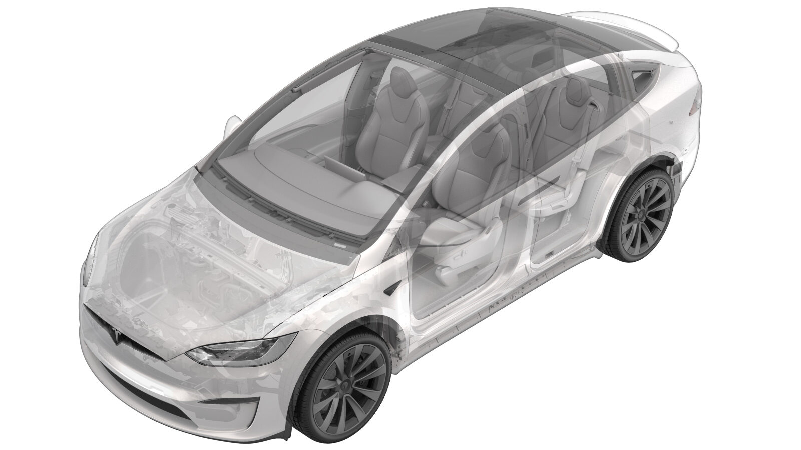
Touchscreen (HW4) (Remove and Replace)
 Correction code
21051402
0.42
NOTE: Unless otherwise explicitly
stated in the procedure, the above correction code and FRT reflect all of the work
required to perform this procedure, including the linked procedures. Do not stack correction codes unless
explicitly told to do so.
NOTE: See Flat Rate Times to learn
more about FRTs and how they are created. To provide feedback on FRT values, email ServiceManualFeedback@tesla.com.
NOTE: See Personal Protection to make sure proper PPE is worn when
performing the below
procedure.
Remove
- Open the RH front door.
- Lower both front windows.
- Move the RH front seat backward.
- Disconnect LV power. See LV Power (Disconnect and Connect).
- Remove the instrument panel service panel. See Service Panel - Instrument Panel (Remove and Replace).
-
Remove the bolts (x2) that attach the touchscreen to the instrument panel carrier.
TIpUse of the following tool(s) is recommended:
- 2 in extension
- 10 mm deep socket
- Ratchet/torque wrench
-
Disconnect the touchscreen motor connectors (x2).
-
Release the tabs (x3) that attach the touchscreen shroud to the touchscreen, and then remove the shroud from the vehicle.
NoteSlide the display outwards until the shroud fully clears the instrument panel and support. Release the bottom tabs and pull upwards.
-
Release the clip that attaches the harness to the touchscreen pivot mechanism arm, and then disconnect the touchscreen coax and power connectors (x2).
NoteSupport the touchscreen and slide it rearwards to access the connectors.TIpUse of the following tool(s) is recommended:
- Clip pry tool
- Pick Miniature Soft Grip, 90 degree tip, 6 in
-
Remove the touchscreen and pivot mechanism from the vehicle.
-
Place the touchscreen and pivot mechanism on a soft and clean working surface.
-
Release the tabs (x3) that attach the touchscreen lower shroud cover to the touchscreen, and then remove the cover from the touchscreen.
NoteSlide the lower shroud cover upwards, and then outwards to remove from the touchscreen.
-
Remove the bolt that attaches the touchscreen ground strap to the touchscreen, and then remove the strap from the touchscreen.
CAUTIONFailure to re-connect the ground strap will result in display functionality issues.NoteInspect the ground strap bolt and replace if damaged.TIpUse of the following tool(s) is recommended:
- Mini Ratchet Bit Set
- Remove the touchscreen pivot mechanism. See .
Install
- Install the touchscreen pivot mechanism. See .
-
Position the touchscreen ground strap on the touchscreen, and then install the bolt that attaches the strap to the touchscreen.
 4 Nm (2.9 lbs-ft)CAUTIONFailure to re-connect the ground strap will result in display functionality issues.NoteInspect the ground strap bolt and replace if damaged.TIpUse of the following tool(s) is recommended:
- Mini Ratchet Bit Set
- Torque Wrench 1/4in Dr Hexagon - 1060071-00-A
-
Position the touchscreen lower shroud cover on the touchscreen, and then install the tabs (x3) that attach the cover to the touchscreen.
NoteSlide the lower shroud cover downwards until the tabs fully engage.
-
Position the touchscreen and pivot mechanism on the instrument panel carrier, and then route the display harness behind the LH side of the touchscreen pivot mechanism.
-
Connect the touchscreen coax and power connectors (x2), and then install the clip that attaches the harness to the touchscreen pivot mechanism arm.
NoteReplace the clip if it is damaged.
-
Position the touchscreen shroud behind the touchscreen, and then install the tabs (x3) that attach the shroud to the touchscreen.
NoteSlide the display downwards until the tabs fully engage.
-
Install the bolts (x2) that attach the touchscreen to the instrument panel carrier.
 11.5 Nm (8.5 lbs-ft)TIpUse of the following tool(s) is recommended:
- 2 in extension
- 10 mm socket
- Ratchet/torque wrench
-
Connect the touchscreen motor connectors (x2).
NoteSlide the touchscreen fully into the instrument panel brackets after securing the connectors.
- Install the instrument panel service panel. See Service Panel - Instrument Panel (Remove and Replace).
- Connect LV power. See LV Power (Disconnect and Connect).
- Close the hood.
- Move the RH front seat to original position.
- Connect a laptop with Toolbox to the vehicle. See Toolbox (Connect and Disconnect).
-
In Toolbox, click the Actions tab, type "display" into the search field, click Display Actuator Test, click Run, and then allow the routine to complete.
NoteSelect ‘X’ at top right of window to close once calibration is successful. Check mechanism wiring and connections if failed.
-
Click Display Mechanism Calibration, click Run, and then allow the routine to complete.
NoteSelect ‘X’ at top right of window to close once calibration is successful.
-
Type "display mech" into the search field, click Display Mech Functional Test, click Run, and then allow the routine to complete.
NoteSelect ‘X’ at top right of window to close once calibration is successful.
- Disconnect the laptop with Toolbox from the vehicle. See Toolbox (Connect and Disconnect).
-
Calibrate the rear doors.
NoteIf the "Calibration Needed" message appears on the vehicle touchscreen, touch and hold Calibrate to calibrate the rear doors.
- Raise the RH front window.
- Close the RH front door.