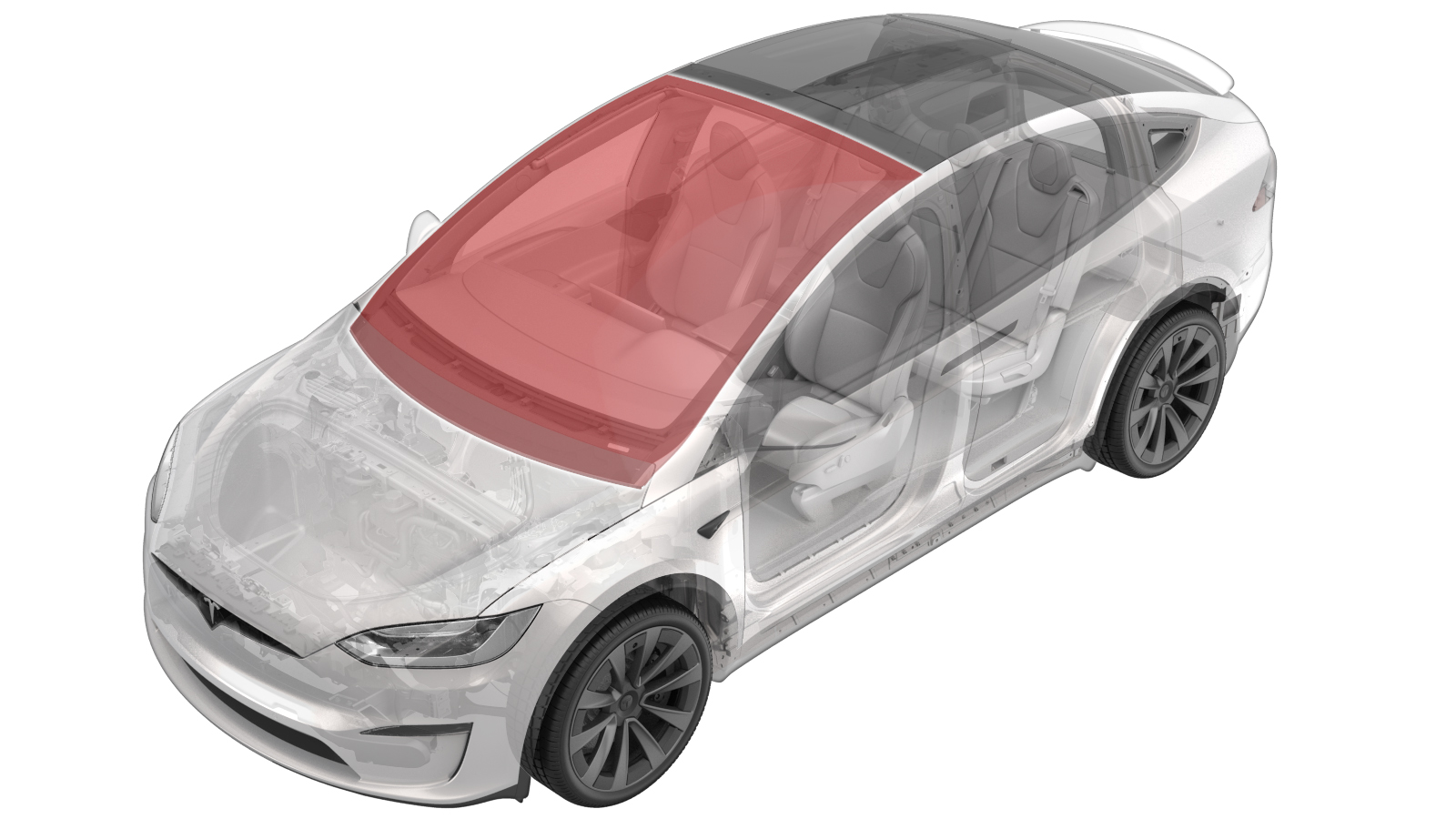
Windshield (Remove and Replace)
 Correction code
10200302
2.22
NOTE: Unless otherwise explicitly
stated in the procedure, the above correction code and FRT reflect all of the work
required to perform this procedure, including the linked procedures. Do not stack correction codes unless
explicitly told to do so.
NOTE: See Flat Rate Times to learn
more about FRTs and how they are
created.
NOTE: See Personal Protection to make sure proper PPE is worn when
performing the below
procedure.
Correction code
10200302
2.22
NOTE: Unless otherwise explicitly
stated in the procedure, the above correction code and FRT reflect all of the work
required to perform this procedure, including the linked procedures. Do not stack correction codes unless
explicitly told to do so.
NOTE: See Flat Rate Times to learn
more about FRTs and how they are
created.
NOTE: See Personal Protection to make sure proper PPE is worn when
performing the below
procedure.
- 2026-06-10: Added warnings to set the drill clutch to 1 when using a drill with the Spider tool.
- 2025-03-26: Added note and caution to make sure vehicle is parked on a flat place.
- 2024-12-10: Added new caution about Pre-Installation Glass Inspection service requirements.
- 2023-08-09: Added reference to camera pitch verification procedure.
- 2024-02-05: Re-structured the procedure.
| Description | Torque Value | Recommended Tools | Reuse/Replace | Notes |
|---|---|---|---|---|
| Bolts (x2) that secure the glare shield |
 1 Nm (.7 lbs-ft) |
|
Reuse | |
| Screws (x4) that secure the mounting plate to the windshield bracket |
0.8 Nm (7 lbs-in) |
Tools for removal:
Tools for installation:
|
Reuse |
Equipment:
- 1571168-00-A - WRD Spider 3 Glass Removal Kit
- 1080599-00-A - Double suction cup handle
Remove
- Open the LH front door and lower both front windows.
- On the touchscreen, tap , and use the left steering wheel scroll wheel to adjust the steering column fully rearward and fully down.
- Move the LH front seat backward.
- Remove the rear view mirror. See Mirror - Rear View (Remove and Replace).
- Remove the rear view mirror harness cover. See Cover - Harness - Rear View Mirror (Remove and Replace).
-
Release the fan harness connector.
-
Release the heater grid harness from the hooks (x2) and the connector retainer.
-
Disconnect the GNSS antenna harness connector.
-
Remove the bolts (x2) that secure the glare shield, and then tilt the shield down and slide the tabs (x2) forward.
TIpUse of the following tool(s) is recommended:
- Torx T10 socket
- Flex head ratchet/flex head torque wrench
- Ratchet/torque wrench
-
Remove the screws (x4) that secure the mounting plate to the windshield bracket.
TIpUse of the following tool(s) is recommended:
- Flex head ratchet/flex head torque wrench
- 4 in extension
- Adapter 1/4in Dr. to 1/4in Hex Bit Quick Change
- Torx T10 bit
-
Release the harness from the windshield.
NoteRelease the harness guide from the windshield retainer. Fully lower the overhead console harness from the windshield.
- Remove the LH and RH upper A-pillar trims. See Trim - A-Pillar - Upper - LH (Remove and Replace).
-
Disconnect the windshield heater connectors (x2).
-
Remove the cowl screen panel. See Panel - Cowl Screen (Remove and Replace).
NoteNo need to separate the wiper hose from the panel.
-
Use an equalizer to separate the datums (x2) from the upper corners of the windshield.
NoteSlide the equalizer up against the datums and carefully tap the equalizer to separate the datums from the windshield.
-
Prepare a WRD Spider 3 glass removal kit (1571168-00-A).
-
Secure the line to the starter tool and push the tool through the urethane at the lower RH side of the windshield.
CAUTIONUse the guard to prevent damage to the dash pad while using the starter tool.CAUTIONEnsure the vehicle is parked on a flat surface for the entirety of the curing process.
-
Pull the line away from the starter tool and wrap the line up and around the exterior of windshield.
NoteEnsure enough length is pulled through. Verify the line sits underneath the glass.
-
Attach the anchor point to the exterior of windshield near the starting point of the handle tool, and secure the line to the anchor once the line is fully wrapped around windshield.
-
Secure the interior side of line to the spider cutting tool.
CAUTIONFollow the instructions on the spider tool. Feed the line through the opening of the cutting tool and tie a knot to secure it in place. If the spindle is not turned the proper direction, the cutting tool will be damaged.
-
Secure the spider cutting tool to the interior side of windshield.
NoteNote the orientation of the cutting line. Make sure the line wraps over the large pully and holds at a 90 degree angle.
-
Install an angle driver to an electric drill and set the drill clutch to 1.
WarningFailure to set the drill clutch to 1 may result in serious injury.
-
Turn the spindle on the cutting tool with the drill to start removing the windshield.
WarningDo not begin cutting the windshield without first setting the drill clutch to 1. Failure to do so may result in serious injury.CAUTIONTake special care in the areas identified that have overlapping panels to prevent damage.NoteMove the cutting tool as needed and keep the line close to a 90° angle. When passing the VIN plate, use a guard to guide the line over VIN to prevent damage.
-
Secure 2 suction cups (1080599-00-A) onto each side of the windshield.
-
With assistance, remove the windshield from the windshield frame.
-
Clean and remove the old adhesive from the windshield frame.
Install
- Remove the new windshield from packaging and set it onto the stands.
- Clean the windshield as needed. Take special caution to the forward-facing camera area to ensure a clear view of the forward-facing camera. See Clean Forward Camera View (Precision Cleaning of Inboard Glass).
-
Apply urethane primer to the windshield and the vehicle body along the old urethane path.
-
Prepare a caulking gun and urethane.
NoteThe opening must be 8mm wide and 14mm tall.
- Apply urethane following the primer path on the windshield.
- With assistance, install the windshield and apply pressure to all four corners of the glass.
-
Check gap and flush measurements.
Note
-
Apply tape to secure the windshield to body while urethane cures.
- Remove the suction cups from the windshield.
-
Install the cowl screen panel. See Panel - Cowl Screen (Remove and Replace).
NoteNo need to separate the wiper hose from the panel.
-
Connect the windshield heater connectors (x2).
- Install the LH and RH upper A-pillar trims. See Trim - A-Pillar - Upper - LH (Remove and Replace).
-
Secure the harness to the windshield.
NoteInstall the harness guide into the windshield retainer.
-
Position the triple camera and install the screws (x4) that secure the mounting plate to the windshield bracket.0.8 Nm (7 lbs-in)TIpUse of the following tool(s) is recommended:
- Digital Torque Screwdriver 0.10Nm - 2.0Nm
- T10 Torx Driver
-
Slide the tabs (x2) into the triple camera assembly and align the datums (x2), and then install the bolts (x2) that secure the glare shield.1 Nm (.7 lbs-ft)TIpUse of the following tool(s) is recommended:
- Torx T10 socket
- Flex head ratchet/flex head torque wrench
- Ratchet/torque wrench
-
Secure the heater grid harness to the hooks (x2) and the connector retainer.
-
Connect the GNSS antenna connector.
-
Secure the fan harness connector.
- Reinstall the latest firmware, or update the firmware if not the latest. See Firmware Reinstall - Touchscreen or Firmware Update.
- Perform the forward facing camera pitch verification. See Camera - Forward Facing (Pitch Verification)
- Install the rear view mirror harness cover. See Cover - Harness - Rear View Mirror (Remove and Replace).
- Install the rear view mirror. See Mirror - Rear View (Remove and Replace).
- On the touchscreen, tap , and use the left steering wheel scroll wheel to adjust the steering column back to original position.
- Move the LH front seat to original position.
- Raise both front windows and close the LH front door.
- Vehicle will need to be driven by customer to complete the calibration procedure. During this time the DAS functions will be completely unavailable.