2023-08-24
Hub - Rear - LH (Remove and Replace)
 Correction code
31030702
0.84
NOTE: Unless otherwise explicitly
stated in the procedure, the above correction code and FRT reflect all of the work
required to perform this procedure, including the linked procedures. Do not stack correction codes unless
explicitly told to do so.
NOTE: See Flat Rate Times to learn
more about FRTs and how they are
created.
NOTE: See Personal Protection to make sure proper PPE is worn when
performing the below
procedure.
Correction code
31030702
0.84
NOTE: Unless otherwise explicitly
stated in the procedure, the above correction code and FRT reflect all of the work
required to perform this procedure, including the linked procedures. Do not stack correction codes unless
explicitly told to do so.
NOTE: See Flat Rate Times to learn
more about FRTs and how they are
created.
NOTE: See Personal Protection to make sure proper PPE is worn when
performing the below
procedure.
Torque Specifications
| Description | Torque Value | Recommended Tools | Reuse/Replace | Notes |
|---|---|---|---|---|
| Nut that attaches the stabilizer bar end link to the rear stabilizer bar |
 55 Nm (40.6 lbs-ft) |
|
Replace | |
| Bolts that attach the rear hub to the knuckle |
 90 Nm (66.4 lbs-ft) |
|
Reuse | |
| Bolts (x2) that attach the caliper to the knuckle |
 125 Nm (92.2 lbs-ft) |
|
Reuse | |
| Bolt that attaches the rear brake hose to the lower aft link |
 6 Nm (4.4 lbs-ft) |
|
Reuse |
Remove
- Raise and support the vehicle. See Raise Vehicle - 2 Post Lift.
- Release the parking brake caliper. See Park Brake Caliper - Release.
- Remove the LH rear wheel center cap.
- Loosen the LH rear axle nut.
- Remove the LH rear wheel. See Wheel Assembly (Remove and Install).
-
Disconnect the Electronic Parking Brake (EPB) harness connector.
CAUTIONDO NOT push down on the red locking tab. Pull the tab away from the connector until the connector is unlocked, and then continue pulling to release the connector.TIpUse of the following tool(s) is recommended:
- Small flat head screwdriver
-
Release the clip that attaches the EPB electrical harness to the LH lower control link.
TIpUse of the following tool(s) is recommended:
- Clip pry tool
-
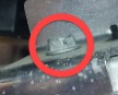
Remove the bolt that attaches the LH rear brake hose to the LH lower aft link.
TIpUse of the following tool(s) is recommended:
- Nutsetter 1/4in Dr. 6in. X 10 mm magnetic deep
-
Remove and discard the nut that attaches the LH rear stabilizer bar end link to the rear stabilizer bar.
NoteBreak the nut loose, and then use a 5 mm socket and ratchet to counter-hold the ball joint to stop the stud from rotating while removing the nut.TIpUse of the following tool(s) is recommended:
- 15 mm socket
- 5 mm hex
-
Loosen the LH rear brake caliper from the rotor, and then remove the bolts (x2) that attach the caliper to the rear knuckle.
NoteUse a S-hook to hang the caliper on the vehicle body if not fully removing. Route the caliper hose so that it does not get caught on the stabilizer bar assembly.TIpUse of the following tool(s) is recommended:
- 3 in extension
- Brake caliper S-hook
- External Torx E18 - 1133187- 01-A
- Flex head ratchet/flex head torque wrench
-
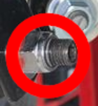
Remove and discard the nut and washer that attach the LH rear drive axle to the hub assembly.
NoteIf an axle washer is not present, procure a washer so it can be installed later in this procedure.TIpUse of the following tool(s) is recommended:
- 1/2" Dr. Electric impact - 1705887-00-A
- 32 mm deep impact socket
-
If installed, remove and discard
the bolt that attaches the brake rotor to the hub.
NoteA new bolt will not be installed.TIpUse of the following tool(s) is recommended:
- 13 mm socket
-
Install the lug nuts (x5) that attach the hub puller to the LH rear brake rotor.
NoteHand tighten the lug nuts only.TIpUse of the following tool(s) is recommended:
- Hydraulic hub puller - 1096075-00-A
-
Use the hub puller to release the LH rear halfshaft from the hub assembly.
TIpUse of the following tool(s) is recommended:
- 17 mm deep socket
- Flex head ratchet/flex head torque wrench
- Remove the lug nuts (x5) that attach the hub puller to the LH rear brake rotor, and then remove the puller from the vehicle.
-
Remove the LH rear brake rotor from the vehicle.
-
Remove the bolts (x4) that attach the LH rear hub to the knuckle, and then remove the hub from the vehicle.
CAUTIONA magnetic field from a pick-up tool or magnetic parts tray could permanently damage the magnetic pattern on the hub/bearing tone ring. Place the hub on a non-magnetic surface after removal.TIpUse of the following tool(s) is recommended:
- 18 mm socket
- 3 in extension
- 3/8in Impact wrench - 1115256-00-A
Install
- If necessary, use IPA wipes to clean the LH rear axle shaft.
-
Apply Molykote M-77 to the outboard side of the LH rear axle shaft.
NoteApply no more than 1 gram of Molykote to the axle shaft.
-
Use IPA wipes to clean the mating surfaces of the LH rear hub and the wheel speed sensor. Allow 1 minute of dry time.
NoteClean the mating surfaces of any debris or grease. Ensure a clean surface for reading of the wheel speed sensor.TIpUse of the following tool(s) is recommended:
- Plastic trim tool
-
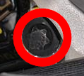
Check the tone ring on the LH rear hub prior to installation.
NoteUse the magnetic field viewing card to ensure that the magnetic field on the tone ring is not damaged. Refer to Toolbox Article 28542 for further information on checking the tone ring: https://toolbox.teslamotors.com/articles/28542.TIpUse of the following tool(s) is recommended:
- Magnetic field viewer card - 1062500-00-A
-
Carefully line up and guide the LH rear axle shaft splines through the LH rear hub and position the hub on the knuckle.
-
With assistance, partially install the bolts (x4) that attach the LH rear hub to the knuckle by hand.
NoteHold down the hub flush to the knuckle while an assistant threads in the hub bolts.
-
Fully torque the bolts (x4) that
attach the LH rear hub to the knuckle.90 Nm (66.4 lbs-ft)CAUTIONDo not damage or bend the axle shaft.NoteTighten down the hub evenly and in a diagonal pattern while torquing the bolts.NoteThe axle shaft splines should be correctly fitted in the hub prior to torquing the bolts.TIpUse of the following tool(s) is recommended:
- 18 mm socket
- 3/8in Impact wrench - 1115256-00-A
- Extension 3/8in Dr. x 11 in
-
Install the LH rear brake rotor on the vehicle.
-
Partially install the new nut and washer that attach the LH rear drive axle to the hub assembly by hand.
Important: Hand tighten the nut only. Do not torque the nut at this time.
-
Remove the LH rear brake caliper from
the S-hook, position the caliper on the rotor, and then install the bolts (x2) that
attach the caliper to the knuckle.125 Nm (92.2 lbs-ft)NoteEnsure the S-hook is removed from the vehicle body once the caliper is installed.TIpUse of the following tool(s) is recommended:
- 3 in extension
- Brake caliper S-hook
- External Torx E18 - 1133187- 01-A
- Flex head ratchet/flex head torque wrench
-
Install the bolt that attaches the LH
rear brake hose to the LH lower aft link.6 Nm (4.4 lbs-ft)TIpUse of the following tool(s) is recommended:
- Nutsetter 1/4in Dr. 6in. X 10 mm magnetic deep
-
Install the clip that attaches the EPB electrical harness to the LH lower control link.
-
Install a new nut that attaches the LH
rear stabilizer bar end link to the rear stabilizer bar.55 Nm (40.6 lbs-ft)NoteUse a 5 mm socket and ratchet to counter-hold the ball joint to stop the stud from rotating while installing the nut. Adjust the end link to align with stabilizer bar. It may be necessary to move the stabilizer bar up and down to get the correct angle to install the end link.TIpUse of the following tool(s) is recommended:
- 15 mm socket
- 5 mm hex
-
Connect the EPB harness connector.
NoteFully seat the connector and then engage the locking tab.
- Install the LH rear wheel. See Wheel Assembly (Remove and Install).
-
Lower the vehicle until the tires are touching the ground.
NoteRaise the lift off locks, and then hold the lock release lever to keep locks free while vehicle is lowered.
-
Fully torque the nut that attaches the LH rear drive axle to the hub assembly.
 245 Nm (180.7 lbs-ft)TIpUse of the following tool(s) is recommended:
- 32 mm deep impact socket
- Ratchet/torque wrench
-
Install the LH rear wheel cap.
NoteVerify the emblem is aligned with the valve stem.
- Hold the brake pedal and select "Park" on the vehicle display to disable EPB service mode.
-
Remove the vehicle from the 2-post lift.
NoteLower the rack arms fully and remove them from under the vehicle. Remove air suspension from "Jack Mode".
- Raise the LH front window.
- Close the LH front door.
- Refer to the Alignment Requirement tables to determine whether an EPAS alignment check (EC) or four wheel alignment check (AC) is necessary. If performed, add the alignment check/adjust as a separate activity. See Alignment Requirement - Suspension.