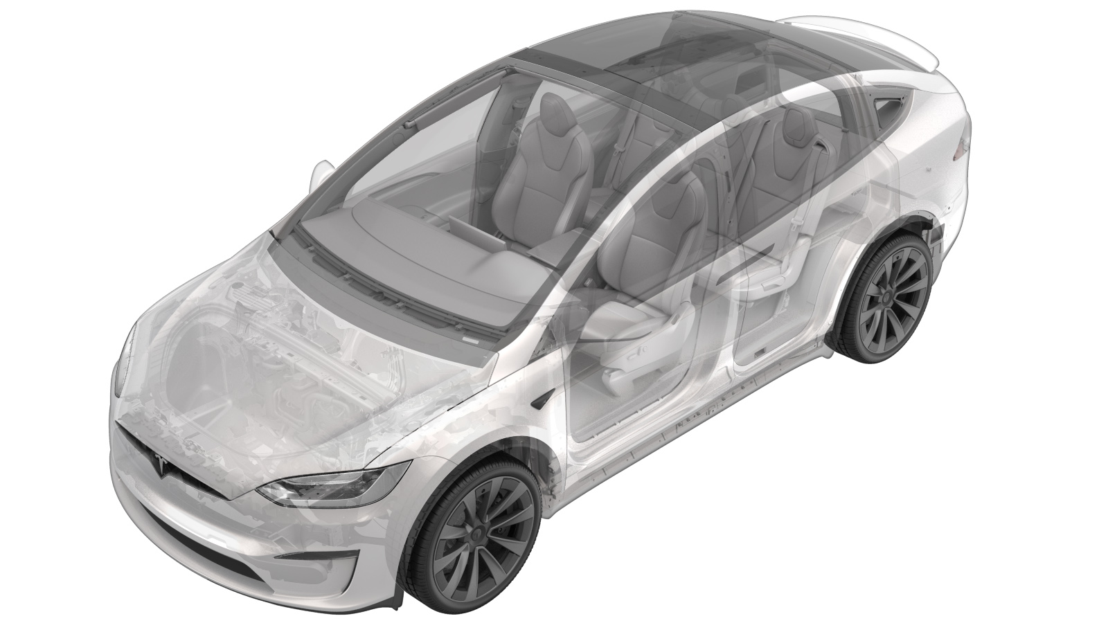
Tire - Front - LH (Tire Purchase)
 Correction code
34021002
0.35
NOTE: Unless otherwise explicitly
stated in the procedure, the above correction code and FRT reflect all of the work
required to perform this procedure, including the linked procedures. Do not stack correction codes unless
explicitly told to do so.
NOTE: See Flat Rate Times to learn
more about FRTs and how they are created. To provide feedback on FRT values, email ServiceManualFeedback@tesla.com.
NOTE: See Personal Protection to make sure proper PPE is worn when
performing the below
procedure.
- 2023-05-23: Added caution about lubricant drying time.
- Remove the LH front wheel. See Wheel Assembly (Remove and Install)
-
Remove valve stem cap
Note1x cap
-
Remove valve stem core
NoteExercise caution as tire rapidly deflates, wear appropriate PPE
-
Place wheel on tire machine and secure
Note1x wheel clamp
-
Rotate tire and wheel so that upper roller is 100mm in front of the valve
-
Break tire beads
NoteUse lubrication around tire and wheel
-
Remove tire from wheel
NoteMake sure to position the TPMS sensor ahead of the tire machine arm
-
Thoroughly lubricate both beads and mount new tire
NoteMake sure to position the TPMS sensor opposite the tire machine arm. If the tire has "outside", "side facing outwards", or a direction of rotation arrow on the sidewall, ensure that the tire is oriented properly
-
Inflate the tire to seat the bead
NoteDo not exceed the pressure indicated on the tire sidewall, Wear PPE
-
Install valve core stem and then remove wheel from mounting machine
-
Mount tire and wheel assembly on balancer
Note1x tire machine wing nut
-
Remove wheel weights
-
Place Wheel/Tire on Balance Machine and secure lock nut
-
Verify tire pressure is set
NoteSet to specification if necessary, Refer to the "Tire and Loading Information" label located on the driver side B-pillar
-
Input wheel dimensions into balancer machine
-
Spin wheel to check balance
-
Install weights in positions indicated by machine
-
Perform check spin
-
Remove tire and wheel assembly from tire balancer
Note1x tire balancer wing nut
- Install the LH front wheel. See Wheel Assembly (Remove and Install)