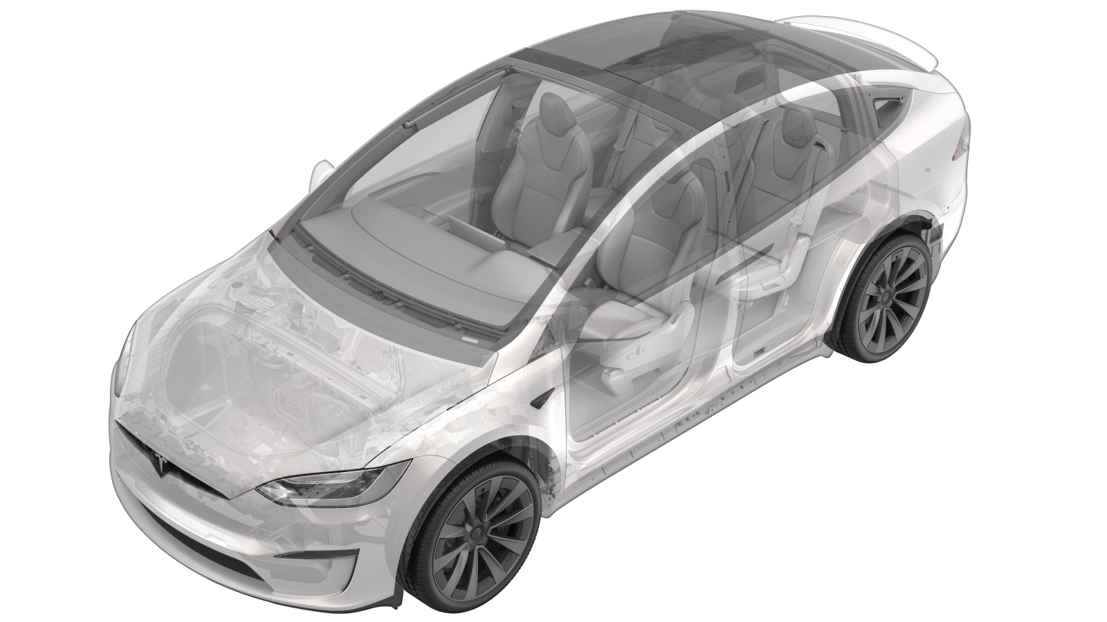
ECU - Charge Port (Remove and Replace)
 Correction code
44015002
0.48
NOTE: Unless otherwise explicitly
stated in the procedure, the above correction code and FRT reflect all of the work
required to perform this procedure, including the linked procedures. Do not stack correction codes unless
explicitly told to do so.
NOTE: See Flat Rate Times to learn
more about FRTs and how they are created. To provide feedback on FRT values, email ServiceManualFeedback@tesla.com.
NOTE: See Personal Protection to make sure proper PPE is worn when
performing the below
procedure.
- 2023-09-18: Optimized the whole procedure in a more efficient way.
Remove
- Open the LH front door and lower the both front windows.
- Move the LH front seat forward.
- Open the LH falcon wing door.
- For 6/7-seat vehicles only: Move the LH Monopost seat forward.
- Remove the LH middle C-pillar trim. See Trim - C-Pillar - Mid - LH (Remove and Replace).
- For 6/7-seat vehicles only: Fold the LH 3rd row seat back into the down position.
- Disconnect the LV power. See LV Power (Disconnect and Connect).
- Remove the LH upper C-pillar trim. See Trim - C-Pillar - Upper - LH (Remove and Replace).
-
Remove the LH C-pillar NVH foam.
CAUTIONBe careful not to damage the NVH foam.
-
Release the clip that attaches the
charge port manual cable release to the LH mid C-pillar zone bracket.
-
Remove the screws (x4) and push clips (x3) that attach the LH mid C-pillar zone
bracket to the vehicle, and then remove the bracket from the vehicle.
TIpUse of the following tool(s) is recommended:
- Torx T20 socket
- 4 in extension
- Clip pry tool
- Cordless Ratchet/Impact Driver
- Universal Joint 1/4in
-
Disconnect the harness connectors (x3)
from the charge port ECU.
-
Remove the bolt that attaches the
charge port ECU to the vehicle, slide the ECU upward to release the clip, and then
remove the ECU from the vehicle.
TIpUse of the following tool(s) is recommended:
- Flex head ratchet/flex head torque wrench
- 10 mm socket
Install
-
Position the charge port ECU into the vehicle, slide the ECU downward to secure the
clip, and then install the bolt that attaches the ECU to the vehicle.
 4 Nm (2.9 lbs-ft)TIp
- Flex head ratchet/flex head torque wrench
- 10 mm socket
- Torque Wrench 1/4in Dr Hexagon - 1060071-00-A
- Universal Joint 1/4in
-
Connect the harness connectors (x3) to the charge port ECU.
CAUTIONOnce the new ECU is installed, immediately start the software reinstall described in the following steps, as delays might cause excessive LV battery drain.
- Connect the LV power. See LV Power (Disconnect and Connect).
-
Release the tabs (x2) and locating
pins (x4) that attach the service panel to the instrument panel.
NoteRelease the top tabs, and then slide the panel rearward.
- Connect a laptop with Toolbox to the vehicle.
- Click the Actions tab, and then search for "Service-Redeploy".
-
Click SERVICE CAN
REDEPLOY, and then click Run and allow the routine
to complete.
NoteClick the "X" at the top right of window to close once complete.NoteThe routine will state pass but the update will continue to run in the background.NoteThe UI will show update progress.
- Disconnect Toolbox and remove the laptop from the vehicle.
-
Position the service panel into the
instrument panel, and then secure the tabs (x2) and locating pins (x4) that attach the
service panel to the instrument panel.
NoteSlide forward to engage the locating pins, and then secure the tabs upward into the instrument panel.
-
Install the screws (x4) and push clips (x3) that attach the LH mid C-pillar zone
bracket to the vehicle.
TIpUse of the following tool(s) is recommended:
- Torx T20 socket
- 4 in extension
- Torque Wrench 1/4in Dr Hexagon - 1060071-00-A
- Cordless Ratchet/Impact Driver
- Universal Joint 1/4in
-
Secure the clip that attaches the charge port manual cable release to the LH mid
C-pillar zone bracket.
- Install the LH C-pillar NVH foam.
- Install the LH upper C-pillar trim. See Trim - C-Pillar - Upper - LH (Remove and Replace).
- For 6/7-seat vehicles only: Move the LH Monopost seat to original position.
-
Hold the LH and RH upper B-pillar buttons in the down position to manually calibrate
the both falcon wing doors.
NoteThe doors must be calibrated and closed for the firmware to pass.
- Move the LH front seat to original position.
- Verify operation of the vehicle charging system.
- Raise both front windows and close the LH front door.