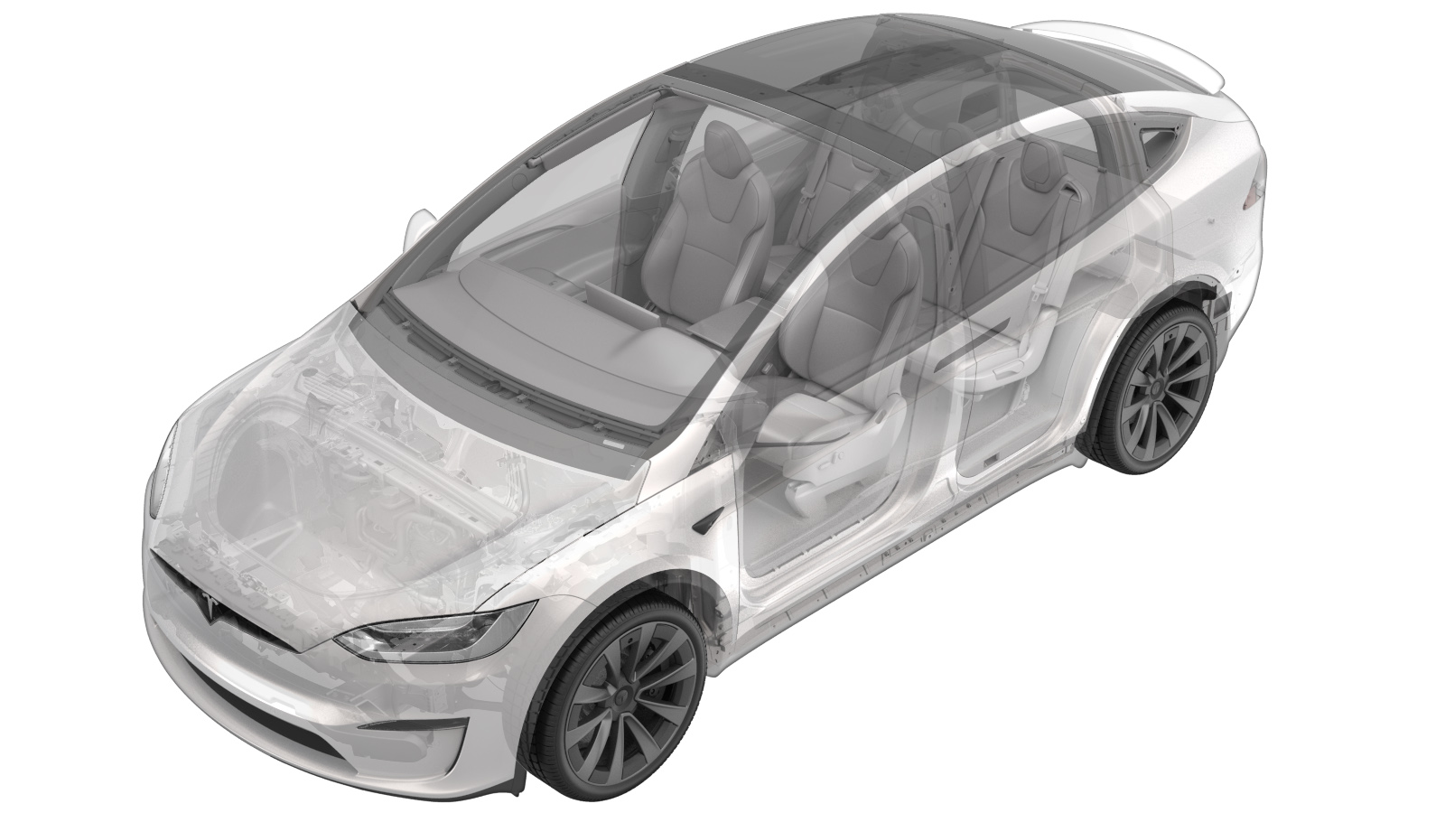
2025-10-20
Decor Assembly - Instrument Panel (2025+) (Remove and Replace)
 Correction code
New
FRT
0.54
NOTE: Unless otherwise explicitly stated in the procedure, the above correction code and FRT reflect all of the work required to perform this procedure, including the linked procedures. Do not stack correction codes unless explicitly told to do so.
NOTE: See Flat Rate Times to learn more about FRTs and how they are created. To provide feedback on FRT values, email ServiceManualFeedback@tesla.com.
NOTE: See Personal Protection to make sure wearing proper PPE when performing the below procedure.
NOTE: See Ergonomic Precautions for safe and healthy working practices.
Note
This procedure describes work that is
specific to 2025+ Model X.
Remove
- Remove the LH middle A-pillar trim. See Trim - A-Pillar - Middle - LH (Remove and Replace).
-
Release the tabs (x6) and remove the
instrument panel LH mid panel.
- Adjust the steering column fully out and fully down.
- Open the RH front door.
- Move the RH front seat backward.
- Disconnect the LV battery power. See LV Power (Disconnect and Connect).
- Remove the RH middle A-pillar trim. See Trim - A-Pillar - Middle - LH (Remove and Replace).
-
Remove the touchscreen assembly. See Touchscreen (HW4) (Remove and Replace).
NoteNo need to remove the pivot mechanism from the touchscreen.
-
Release the tabs (x4) and remove the
instrument panel closeout panel.
-
Release the tabs (x14) and datums (x2)
and remove the instrument panel RH mid panel.
-
Release the clips (x21) and datums
(x6), then disconnect the electrical connectors (x2), and then remove the instrument
panel décor trim assembly from the vehicle.
NoteRelease the connector clip from the instrument panel carrier first, and then disconnect the connector from the instrument panel harness.
Install
-
Connect the electrical connectors
(x2), then secure the clips (x21) and datums (x6) to install the instrument panel décor
trim assembly to the vehicle.
NoteConnect the ambient bright harness, and then secure each connector clip to the instrument panel carrier.
- Install the RH middle A-pillar trim. See Trim - A-Pillar - Middle - LH (Remove and Replace).
-
Secure the tabs (x14) and datums (x2)
to install the instrument panel RH mid panel.
-
Secure the tabs (x4) to install the
instrument panel closeout panel.
- Install the touchscreen assembly. See Touchscreen (HW4) (Remove and Replace).
- Connect the LV battery power. See LV Power (Disconnect and Connect).
- Move the RH front seat to its original position.
-
Hold the upper B-pillar button in the
down position to manually calibrate the RH falcon wing door.
- Close the RH front door.
-
Secure the tabs (x6) to install the
instrument panel LH mid panel.
- Install the LH middle A-pillar trim. See Trim - A-Pillar - Middle - LH (Remove and Replace).
- Adjust the steering column back to original position.
- Move the LH front seat to its original position.
-
Hold the upper B-pillar button in the
down position to manually calibrate the LH falcon wing door.
- Locally connect a laptop with Toolbox 3 to the vehicle. See Toolbox (Connect and Disconnect).
- Click the Actions tab, type "RGB addressing dash" into the search field, click TEST-SELF_VCRIGHT_X_DASH-RGB-SELF-ADDRESSINGvia Toolbox: (link), click Run, and allow the routine to complete.
- Disconnect the laptop.
- Reinstall the vehicle firmware. See Firmware Reinstall - Touchscreen.