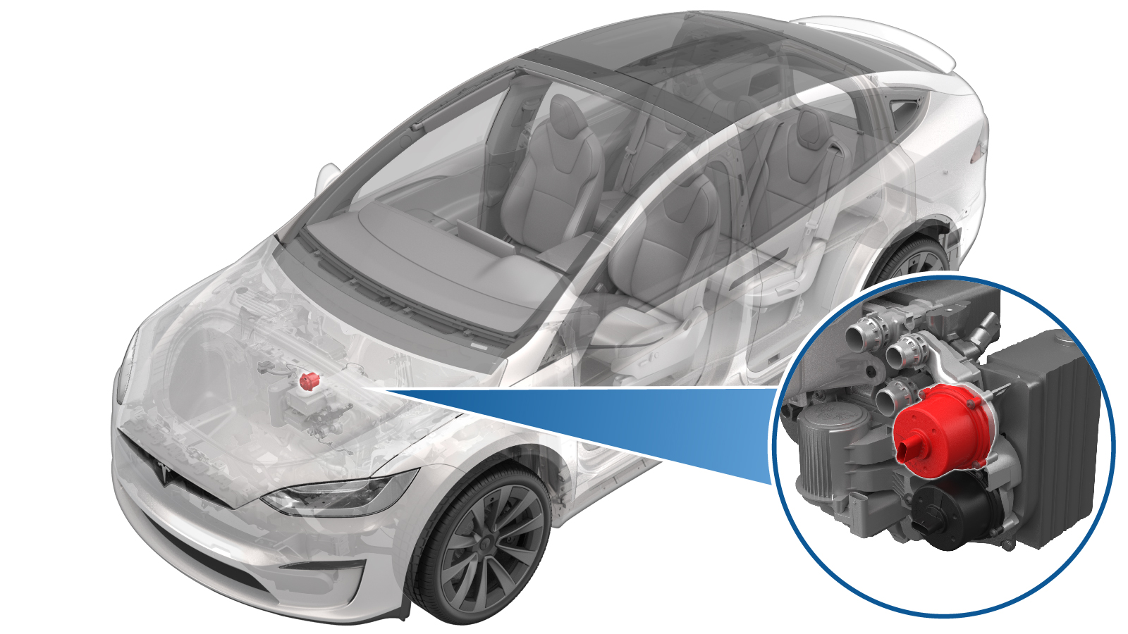
Pump - Coolant - Powertrain - Supermanifold (Remove and Replace)
 Correction code
18401902
1.25
NOTE: Unless otherwise explicitly
stated in the procedure, the above correction code and FRT reflect all of the work
required to perform this procedure, including the linked procedures. Do not stack correction codes unless
explicitly told to do so.
NOTE: See Flat Rate Times to learn
more about FRTs and how they are
created.
NOTE: See Personal Protection to make sure proper PPE is worn when
performing the below
procedure.
Correction code
18401902
1.25
NOTE: Unless otherwise explicitly
stated in the procedure, the above correction code and FRT reflect all of the work
required to perform this procedure, including the linked procedures. Do not stack correction codes unless
explicitly told to do so.
NOTE: See Flat Rate Times to learn
more about FRTs and how they are
created.
NOTE: See Personal Protection to make sure proper PPE is worn when
performing the below
procedure.
- 2025-07-28: Added step to set pump type configuration to DUAL_MIX.
- 2024-04-24: Removed the thermal test steps and updated the way of performing the routines from using Toolbox to using the touchscreen.
Torque Specifications
| Description | Torque Value | Recommended Tools | Reuse/Replace | Notes |
|---|---|---|---|---|
| Screws (x4) that attach the powertrain coolant pump to the supermanifold |
 1.8 Nm (1.3 lbs-ft) |
|
Reuse |
Remove
-
Place the vehicle on the 2-post
lift.
TIpEnsure the vehicle is not charging.
- Open the LH front door and lower the LH front window.
- Place the vehicle in Service Mode by using the touchscreen. See Service Mode (Enable and Disable).
- Unlock the vehicle gateway. See Gateway (Unlock).
- On the touchscreen, tap the Service Mode "wrench" (at the bottom of the touchscreen UI), and then tap , click Run, and allow the routine to complete.
- Remove the underhood storage unit. See Underhood Storage Unit (Remove and Install).
- Disconnect the LV battery power. See LV Power (Disconnect and Connect).
- Remove the LV battery. See Battery - LV (Remove and Replace).
- Remove the front body controller module. See Module - Body Controller - Front (Remove and Replace).
- Remove the front aero shield panel. See Panel - Aero Shield - Front (Remove and Replace).
-
Place a coolant catcher below the RH
front of vehicle.
- Lower the vehicle until the tires are touching the ground.
-
Place absorbent material on the top of
the front drive unit and under the coolant hoses at rear of the supermanifold.
-
Disconnect the sensor for the
powertrain supply hose.
-
Disconnect the powertrain supply hose
from supermanifold, and plug the ends of fittings as soon as possible to avoid coolant
loss.
-
Disconnect the low pressure PT sensor
connector and release the harness from supermanifold.
-
Release the clips (x2) that attach the
thermal harness to the supermanifold.
-
Release the connectors (x2) that
attach the thermal harness to the powertrain coolant pump and the chiller coolant pump,
and then move the harness away from the rear of supermanifold.
-
Remove the screws (x4) that attach the
powertrain coolant pump to the supermanifold.
TIpUse of the following tool(s) is recommended:
- Mini Ratchet Bit Set
-
Remove the powertrain coolant pump
from the supermanifold.
NoteMake sure both o-rings (inner purple, and outer black) come off with the old pump.
Install
-
Lubricate both O-rings with silicone lubricant.
-
Align the datum of supermanifold with
the slot of the powertrain coolant pump, then seat the pump fully into the
supermanifold.
CAUTIONDo not use screws to force the pump into the supermanifold.
-
Install the screws (x4) that attach the powertrain coolant pump to the
supermanifold.1.8 Nm (1.3 lbs-ft)TIpUse of the following tool(s) is recommended:
- Mini Ratchet Bit Set
-
Route the thermal bar harness between the powertrain coolant pump and the chiller
coolant pump, then secure the connectors (x2) that attach the thermal harness to the
powertrain coolant pump and the chiller coolant pump.
-
Secure the clips (x2) that attach the
thermal harness to the supermanifold.
-
Secure the harness to supermanifold,
and connect the low pressure PT sensor connector.
-
Remove the plugs on the ends of
fittings, and then connect the powertrain supply hose to the supermanifold.
NotePerform a push-pull-push test to make sure that the hose is fully secured.
-
Connect the sensor for the powertrain
supply hose.
- Remove the absorbent material which is on the top of the front drive unit and under the coolant hoses at rear of the supermanifold.
- Clean the area and wipe away any residual fluid.
- Remove the front body controller module. See Module - Body Controller - Front (Remove and Replace).
- Perform a cooling system vacuum refill. See Cooling System (Vacuum Refill).
- Install the LV battery. See Battery - LV (Remove and Replace).
- Connect the LV battery power. See LV Power (Disconnect and Connect).
- Enable Service Mode Plus. See Service Mode Plus.
- Unlock the vehicle gateway. See Gateway (Unlock).
-
Inspect the current coolant pump
configuration: in Service Mode Plus, select and then set the coolant pump configuration to DUAL_MIX.
Figure 1. Model 3 shown, other vehicle models similar. -
On the touchscreen, perform the
following steps:
- Exit Service Mode or disconnect the laptop if applicable (see 0005 - Service Modes).
- Install the front aero shield panel. See Panel - Aero Shield - Front (Remove and Replace).
- Hold the B-pillar button in the down position to manually calibrate the LH and RH falcon wing doors.
-
Inspect the coolant level, top off as
necessary, and then install the coolant bottle cap.
NoteEnsure that the coolant level is at the "Max" line.
- Install the underhood storage unit. See Underhood Storage Unit (Remove and Install).
- Raise the LH front window and close the LH front door.