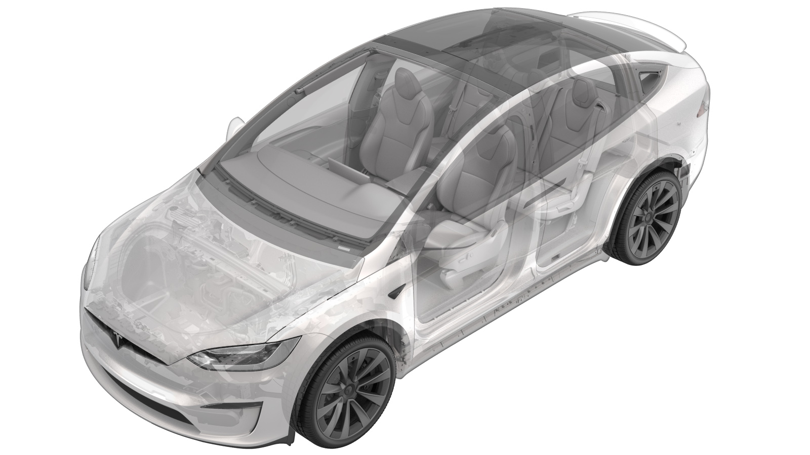
Harness - LV - Front - HV Battery (Remove and Replace)
 Correction code
16300022
6.35
NOTE: Unless otherwise explicitly
stated in the procedure, the above correction code and FRT reflect all of the work
required to perform this procedure, including the linked procedures. Do not stack correction codes unless
explicitly told to do so.
NOTE: See Flat Rate Times to learn
more about FRTs and how they are
created.
NOTE: See Personal Protection to make sure proper PPE is worn when
performing the below
procedure.
Correction code
16300022
6.35
NOTE: Unless otherwise explicitly
stated in the procedure, the above correction code and FRT reflect all of the work
required to perform this procedure, including the linked procedures. Do not stack correction codes unless
explicitly told to do so.
NOTE: See Flat Rate Times to learn
more about FRTs and how they are
created.
NOTE: See Personal Protection to make sure proper PPE is worn when
performing the below
procedure.
- 2023-08-03: Updated LV DC header bolts torque.
Remove
- Remove the HV battery. See HV Battery (AWD) (Remove and Install).
-
Secure PCS Flush adapter to PCS inlet
hose coupling.
NoteRemove plugs as required, Verify fully seated, Perform push-pull-push test.
-
Secure coolant cart flush hose to
regulator and PCS Flush adapter.
NoteVerify regulator valve is closed, Pressure regulator is not adjustable (set at 20 psi).
-
Secure PCS Drain adapter to the end of
the PCS outlet hose.
NoteVerify valve is closed, Remove plug as required, Verify fully seated, Perform push-pull-push test.
-
Secure coolant cart drain hose to PCS
drain adapter and coolant drain container.
-
Open valve on PCS Drain adapter.
-
Connect shop air to regulator.
NoteMake sure regulator valve is closed prior to connecting shop air.
-
Slowly open valve on pressure
regulator and allow coolant to drain out of HV battery.
NoteAllow coolant to drain.
-
Close valve on pressure regulator once
no more coolant is draining .
-
Close valve on PCS Drain
adapter.
-
Remove cart drain hose from PCS Drain
adapter.
-
Remove PCS Drain adapter from end of
PCS outlet hose.
Note1x spring clip.
-
Remove cart flush hose from PCS Flush
adapter.
-
Remove PCS Flush adapter from PCS
inlet coupling.
Note1x spring clip.
-
Remove clip securing PCS outlet hose
to HV battery.
Note1x clip.
-
Release PCS outlet hose from HV
battery.
Note1x spring clip.
-
Remove all items from pockets and
ensure not wearing metal items.
-
Inspect HV insulating gloves.
NoteCheck gloves for damage prior to use, Refer to service document TN-15-92-003, for information on inspecting HV gloves.
-
Put on HV insulating gloves and
leather over gloves.
- Remove the pyrotechnic battery disconnect. See Pyrotechnic Battery Disconnect (Remove and Replace).
-
Remove fasteners securing front access
cover to HV battery assembly.
Note17x bolts, T25, 4.5 Nm, Discard after removal.
-
Separate HV front access cover sealant
to allow removal.
NoteOnly use non-conductive non-marring tools to break sealant, Be cautious not to severely bend and deform the access cover, Be cautions and do not damage the internal components or HV battery casing.
-
Disconnect coolant hoses from PCS and
install plugs.
Note2x hoses, Use the special tool to release the 2x clips on each hose, Support front access cover with non-conductive material as needed, Use a shop towel to catch any minimal excess coolant.
-
Remove front access cover from HV
battery.
-
Disconnect PCS to DC bus HV
connector.
Note1x connector, Release the locking tab by pulling upward, May need plastic trim tool to help lift the connector upward.
-
Disconnect PCS logic connector from
PCS.
Note1x connector.
-
Disconnect PCS LV DC power harness
connector.
Note1x connector, Release the locking tab by pulling upward, May need plastic trim tool to help lift the connector upward.
-
Disconnect AC filter HV harness
connector from PCS.
Note1x connector, Release the locking tab by pulling upward, May need plastic trim tool to help lift the connector upward.
-
Release AC Filter harness clips.
Note3x clips.
-
Remove bolts securing PCS to mounting
tray.
Note6x bolts, 8mm, 6 Nm, Ensure ONLY the 8mm fasteners are removed, Do not remove the T30 fasteners.
-
Lift PCS up and out of front ancillary bay
area and remove from vehicle.
NoteShift PCS left to clear lip of battery enclosure then straight up to remove.
-
Install PCS mounting tray onto front
ancillary bay area.
Note6x bolts, 10mm, 8 Nm.
-
Release HVcon 6 pin carrier
connection.
Note1x locking connector, Disengage locking tab and release connector.
-
Release HVcon FDU carrier
connection.
Note1x locking connector, Disengage locking tab and release connector.
-
Release HVcon 6 pin carrier connection
from clipping point.
Note1x clip, Release from clipping location.
-
Remove FDU HV header.
Note2x bolts, EP10, 10 Nm, Gently separate FDU hv header.
-
Release bolts securing HVcon 0 degree
FDU carrier and remove.
Note2x bolts, 13mm, 5nm +60 degrees, Discard fasteners after removal.
-
Release HVcon 6 pin carrier cable from
fuse.
Note1x nut, 8mm, 4.5 Nm, Do not drop fastener, Move cable aside.
-
Release HVcon 6 pin carrier cable from
inductor coil.
Note1x nut, 7mm, 2.5 Nm, Do not drop fastener, Move cable aside.
-
Disconnect HVC logic connector.
-
Remove nuts securing HVC to front
stack tray.
Note4x nuts, 10mm, 5.1 Nm.
-
Shift HVC for access to the remaining
outboard connector.
NoteLift HVC upward off of studs, then shift HVC inboard and rotate front edge upward to create clearance.
-
Disconnect outboard HV pack main
harness connector and remove HVC from vehicle.
Note1x connector, Depress locking tab and rotate lever arm to release, Be careful as there is very little slack in the harness.
-
Remove LV DC harness ground
bolt.
Note1x bolt, 10mm, 10 Nm.
-
Release LV DC header from battery
pack.
Note3x bolts, T20, 2.5 Nm.
-
Release clips securing LV DC harness
and remove assembly.
Note4x clips, Wear electrical protective gloves, Carefully release clips and guide cable over and out, Be cautious and do not damage any components.
Install
-
Install LV DC harness into battery pack.
Note4x clips, Carefully guide the harness in and secure the clips, Be cautious and do not damage any components.
-
Secure LV DC header onto battery pack.
Note3x bolts, T20, 2.5 Nm.
-
Secure LV DC harness ground bolt .
Note1x bolt, 10mm, 10 Nm.
-
Secure outboard HV pack main harness connector to HVC.
Note1x connector, Rotate lever arm to secure locking tab, Be careful as there is very little slack in the harness.
-
Shift HVC down onto studs for installation.
NoteBe mindful not to pinch surrounding wiring and connectors, Rotate HVC under DC busbar staying high to clear studs, then lower to install position.
-
Install nuts securing HVC to front stack tray.
Note4x nuts, 10mm, 5.1 Nm.
-
Connect HVC logic connector.
Note1x connector, Release locking tab then push the handle downward to release connector.
-
Secure HVcon 6 pin carrier cable onto inductor coil.
Note1x nut, 7mm, 2.5 Nm, Do not drop fastener.
-
Secure HVcon 6 pin carrier cable onto fuse.
Note1x nut, 8mm, 4.5 Nm, Do not drop fastener.
-
Cleaning mating surfaces of the FDU HVcon 0 degree carrier.
NoteAllow 1 min for IPA to dry.
-
Install bolts securing FDU HVcon 0 degree carrier.
Note2x bolts, 13mm, 5nm +60 degrees, Install new fasteners.
-
Install FDU HV header.
Note2x bolts, EP10, 10 Nm.
-
Perform Hioki impedance test at the HV joints of the FDU HVcon 0 degree
carrier.
Note2x HV joint, Verify meter has been properly zero adjusted prior to usage, The acceptable resistance is below d 0.045 mΩ (45 μΩ), If the resistance is greater than 0.045 mΩ (45 μΩ), there is too much resistance in the High Voltage joint. Remove the fastener, clean areas with isopropyl alcohol, install fastener back and test again.
-
Secure HVcon FDU carrier connection.
Note1x connector, Fully engage locking tab.
-
Secure HVcon 6 pin carrier connection onto clipping point.
Note1x clip.
-
Secure HVcon 6 pin carrier connection.
Note1x connector, Fully engage locking tab.
-
Install PCS to front ancillary bay area.
NoteShift PCS under lip of battery enclosure.
-
Install fasteners securing PCS to mounting tray.
Note6x bolts, 8mm, 6 Nm.
-
Secure AC Filter harness clips.
Note3x clips.
-
Connect AC filter HV harness connector to PCS.
Note1x connector, Push down to secure locking tab.
-
Connect PCS LV DC power harness connector.
Note1x connector, Push down to secure locking tab.
-
Connect PCS logic connector to PCS.
Note1x connector.
-
Connect PCS to DC bus HV connector.
Note1x connector, Push down to secure locking tab.
-
Clean sealing surface of HV battery front access panel.
NoteClean sealant and allow for re-seal, Only use non-conductive non-marring tools, Use ESD vacuum and remove all debris.
-
Clean sealing surface of front access cover.
NoteCheck cover for deformation, Bend cover back to original form, if cover is warped or damaged excessively then proceed to a replacement instead.
-
Prepare caulking gun and adhesive, Cut the sealant tip.
NoteCut tip at an angle to allow for easier application.
-
Apply sealant onto the sealing surface of the front access panel.
NoteFollow original bead line, Replace seal if originally equipped.
-
Position front cover for installation and secure hoses to PCS.
Note2x hoses, 2x clips on each hose, Recommend assistance, Secure hoses while holding cover, Remove plugs.
-
Install front access cover to HV battery.
-
Install fasteners securing front access cover to HV battery assembly.
Note17x bolts, T25, 4.5 Nm, Install new fasteners, Allow proper time for sealant to cure, Refer to adhesive work instructions.
- Measure the voltage across the pyrotechnic battery disconnect mount points, and then install the pyrotechnic battery disconnect. See Pyrotechnic Battery Disconnect (Remove and Replace).
-
Secure coolant leak test adapter to PCS inlet coupling.
NoteThis adapter is connected to regulated air line adapter, Make sure the locking tab is fully seated, Perform push-pull-push test.
-
Secure closed ended coolant leak test adapter to PCS outlet coupling.
NotePerform push-pull-push test.
-
Secure pressure test fixture hose to leak test adapter.
-
Secure compressed air line to pressure test fixture.
NoteMake sure valves are closed on pressure regulator.
-
Open the regulator valve then slowly adjust regulator to 50 psi.
NoteUse caution due to high pressure, Make sure to wear safety glasses and personal protection equipment.
-
Open the 2nd valve slowly.
NoteSlowly allow air to enter system.
-
Allow 1 minutes and 50 seconds for the pressure to stabilize .
NoteAllow 1 minutes and 50 seconds (110 seconds) for pressure to stabilize.
-
Close the regulator valve.
-
Record start pressure value.
-
Allow 4 minutes to test.
-
Record end pressure value.
NoteIf pressure did not drop more than 0.35 psi, continue to next step, If pressure dropped more than 0.35 psi, then inspect for leaks and retest.
-
Release compressed air line from pressure test fixture.
-
Open the regulator valve slowly.
NoteSlowly allow air to leave the system.
-
Release pressure test fixture hose from coolant leak test adapter.
-
Remove coolant leak test adapter from PCS inlet coupling.
-
Remove closed ended coolant leak test adapter from PCS outlet coupling.
-
Secure PCS outlet hose to HV battery.
Note1x spring clip, Perform push-pull-push test.
-
Install clip securing PCS outlet hose to HV battery.
Note1x clip.
- Install the HV battery. See HV Battery (AWD) (Remove and Install).