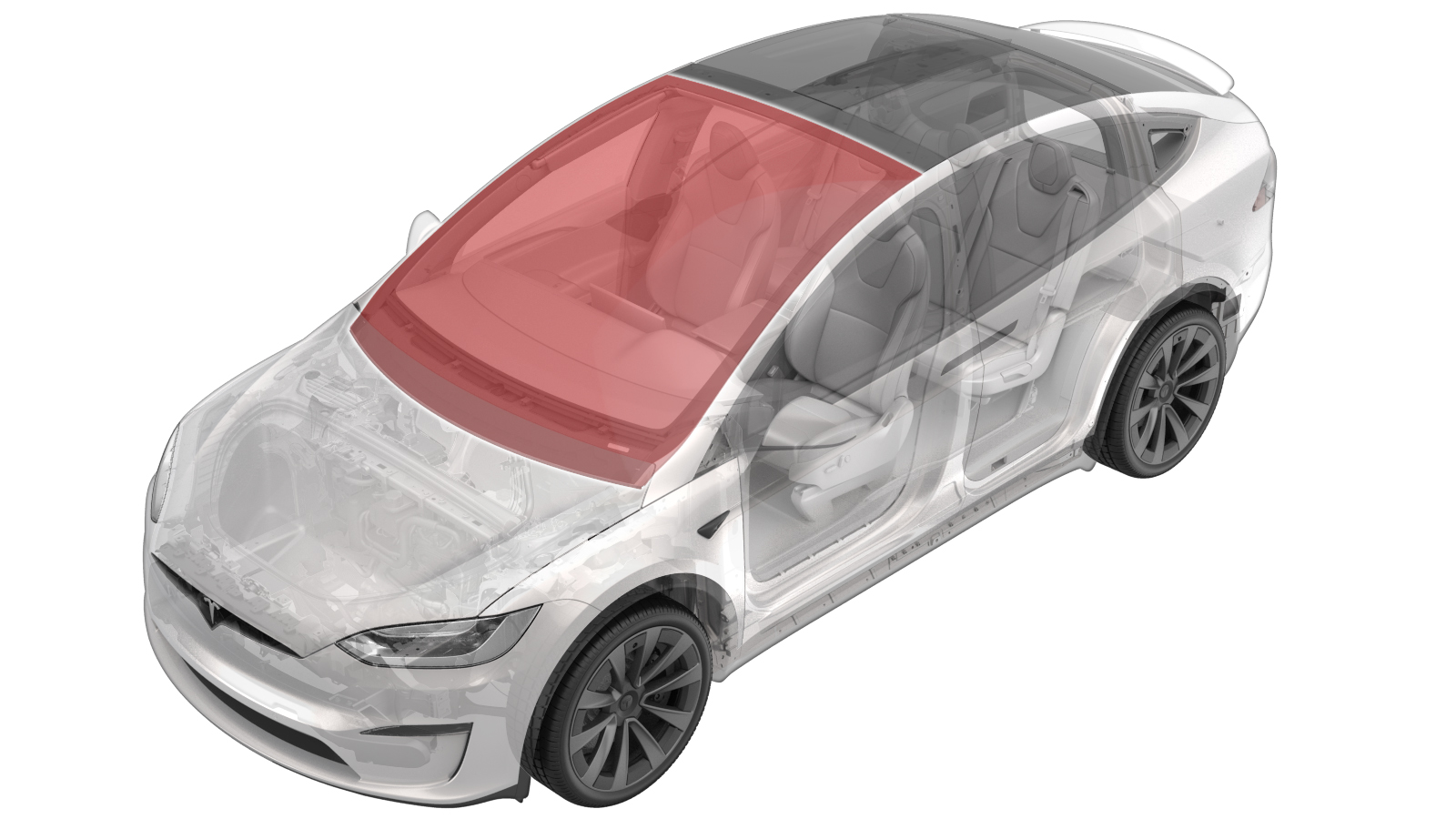
Windshield (Reuse Humidity and Temperature Sensor) (Remove and Replace)
 Correction code
10200312
NOTE: Unless otherwise explicitly
stated in the procedure, the above correction code and FRT reflect all of the work
required to perform this procedure, including the linked procedures. Do not stack correction codes unless
explicitly told to do so.
NOTE: See Flat Rate Times to learn
more about FRTs and how they are
created.
NOTE: See Personal Protection to make sure proper PPE is worn when
performing the below
procedure.
Correction code
10200312
NOTE: Unless otherwise explicitly
stated in the procedure, the above correction code and FRT reflect all of the work
required to perform this procedure, including the linked procedures. Do not stack correction codes unless
explicitly told to do so.
NOTE: See Flat Rate Times to learn
more about FRTs and how they are
created.
NOTE: See Personal Protection to make sure proper PPE is worn when
performing the below
procedure.
- 2025-03-26: Added note and caution to make sure vehicle is parked on a flat place.
- 2024-12-10: Added new caution about Pre-Installation Glass Inspection service requirements.
Remove
- Move the steering column fully rearward and down.
- Move the driver seat rearward.
- Remove the lower camera cover. See Camera Cover - Lower (Remove and Replace).
- Remove the rear view mirror. See Mirror - Rear View (Remove and Replace).
- Remove the rear view mirror harness cover. See Cover - Harness - Rear View Mirror (Remove and Replace).
-
Disconnect the HVAC sensor connector.
-
Remove and discard the screws (x2) that attach the HVAC sensor to the windshield bracket.
 0.12 Nm (1 lbs-in)CAUTIONThe fasteners are small. Make sure not to drop or misplace them.CAUTIONMake sure to use the correct Phillips screwdriver. If the screwdriver is too large, the fastener will round out.TIpUse of the following tool(s) is recommended:
- Phillips PH00
-
Use a pocket screwdriver to gently pry on the HVAC sensor to release the foam from the adhesive, and then remove the sensor from the windshield bracket.
-
Disconnect the fan harness connector.
-
Release the heater grid harness from the harness guides (x2) and connector retainer.
-
Disconnect the harness connector for the GNSS antenna.
-
Remove the bolts (x2) and release the tabs (x2) that attach the glare shield assembly to the windshield, and then release the glare shield from the windshield.1 Nm (.7 lbs-ft)NoteTilt the glare shield down and slide the tabs forward.TIpUse of the following tool(s) is recommended:
- Torx T10 bit
-
Remove the screws (x4) that attach the mounting plate to the windshield.0.8 Nm (7 lbs-in)NoteAllow the camera to hang by the harness.TIpUse of the following tool(s) is recommended:
- Torx T10 bit
-
Release the harness guide from the windshield retainer, and then fully lower the overhead console harness from the windshield.
- Remove the LH instrument panel end cap. See End Cap - Instrument Panel - LH (Remove and Replace).
- Remove the LH middle A-pillar trim. See Trim - A-Pillar - Middle - LH (Remove and Replace).
- Remove the LH sun visor bezel A-pillar trim. See Trim - A-Pillar - Sun Visor Bezel - LH (Remove and Replace).
- Remove the LH upper A-pillar trim. See Trim - A-Pillar - Upper - LH (Remove and Replace).
- Repeat step 15 through step 18 for the RH side of the vehicle.
-
Disconnect the windshield heater connectors (x2).
- Remove the rear underhood apron. See Underhood Apron - Rear (Remove and Replace).
- Remove the LH and RH underhood aprons. See Underhood Apron - LH (Remove and Replace).
- Remove the cowl screen panel. See Panel - Cowl Screen (Remove and Replace).
-
Use an equalizer to separate the datums (x2) from the windshield.
NoteSlide the equalizer up against the datums, and then carefully tap the equalizer to separate from windshield.NoteThe datums are located at each upper corner of the windshield.
-
Prepare the WRD Spider 3 glass removal kit.
TIpUse of the following tool(s) is recommended:
- WRD Spider 3 - 1571168-00-A
-
Secure the wire to the starter tool and push the tool through the urethane at the RH lower side of the windshield assembly.
CAUTIONUse the guard to prevent damage to the dash pad while using the starter tool.CAUTIONEnsure the vehicle is parked on a flat surface for the entirety of the curing process.
-
Release the line from the starter tool and wrap the line around the exterior of the windshield.
NotePull the line away from the starter tool. Make sure enough length is pulled through.NoteVerify the line sits underneath the glass
-
Attach an anchor point to the exterior of the windshield, and then secure the line.
NoteAttach line to the anchor once fully wrapped around windshield. Place the anchor near the starting point of the handle tool.
-
Secure the interior side of the line to the Spider cutting tool.
NoteFollow the instructions on the Spider tool. Feed the line through the opening of the cutting tool and tie a knot to secure the line in place. If the spindle is not turned the proper direction, the cutting tool will be damaged.
-
Secure the Spider cutting tool to the interior side of the windshield.
NoteNote the orientation of the cutting line. Make sure the line wraps over the large pulley and holds a 90 degree angle.
-
Secure the angle driver to the electric drill.
-
Turn the spindle on the cutting tool with the drill to start remove the windshield.
NoteMove the cutting tool as needed, keeping the line close to a 90 degree angle.CAUTIONWhen passing the VIN plate, use the guard to guide the line over the plate to prevent damage.CAUTIONTake special care in the areas identified that have overlapping panels to prevent damage.
-
With assistance, remove the windshield from the vehicle.
NoteHave 3 others aid in removal of the windshield.
Replace Graphene Block
-
Prepare the ESD kit.
NoteRefer to TN-14-92-003, “Electrostatic Discharge Tool”.CAUTIONImproper use of the ESD kit can result in damage to the car computer.CAUTIONMake sure that the ESD foam container is free of debris so that the car computer is not damaged in a later step.
-
Place the ESD mat flat onto a workbench so that the button connector is closest to the grounding point (outlet, vehicle chassis, etc.).
NoteIf the component being worked on is too large to fit on the mat, use the alligator clip to connect the component directly to a ground source.
-
Snap the button connector on the ground cord to the button connector on the ESD mat.
NoteMake sure the connector is securely fastened to the ESD mat.
-
Remove the alligator clip adapter from the end of the wrist strap to expose the banana plug.
-
Connect the banana plug on the wrist strap to the ground cord
-
Connect the ground cord to a ground source.
NotePer TN-14-92-003-R1:
- Service Centers with NEMA 5-15 outlets:
- Plug the ground indicator into the outlet and confirm the 2 lights on the right are lit.
- Remove the alligator clip adapter from the end of the ground cord to expose the banana plug.
- Plug the banana plug on the ground cord into the ground indicator.
- Service Centers with grounded, non-NEMA 5-15 outlets:
- Plug the appropriate adapter into the outlet.NoteService Centers with grounded, non-NEMA 5-15 outlets need to supply an adapter suitable to connect the ground indicator to their regional outlet type. If you are unable to obtain an adapter, contact ServiceTooling@teslamotors.com for assistance.
- Plug the ground indicator into the adapter and confirm the 2 lights on the right are lit.
- Remove the alligator clip adapter from the end of the ground cord to expose the banana plug.
- Plug the banana plug on the ground cord into the ground indicator.
- Plug the appropriate adapter into the outlet.
- Service Centers with non-grounded outlets:
- Clip the alligator clip adapter on the ground cord onto any unpainted metal part of the vehicle.
- Service Centers with NEMA 5-15 outlets:
-
Place the HVAC sensor on the ESD mat.
-
Remove the graphene foam block from the HVAC sensor.
NoteApply heat to the area around the adhesive, and then gently lift up with tweezers.
-
Install the graphene foam block onto the HVAC sensor.
NoteMake sure the block is installed inside the gold square.
-
Remove the ESD wrist strap.
Install
- Clean the windshield as needed. Take special caution to the forward-facing camera area to ensure a clear view of the forward-facing camera. See .
- Clean and remove old adhesive from the windshield frame.
-
Apply urethane primer to the windshield and vehicle body along the urethane path and in areas that were damaged during removal of the windshield assembly.
CAUTIONBe careful not to damage the headliner during application.NoteAllow the primer to dry for at least 2 minutes.
-
Apply urethane to the windshield following the original path.
NoteMake sure that the urethane bead has a triangular cross-section of approximate width 8 mm and height 14 mm.
- With assistance, install the new windshield assembly onto the vehicle, and apply pressure to all four corners of the glass.
- Check the gap and flush of the windshield assembly to the body before fully seating the windshield assembly.
- Fully seat the windshield assembly, check the gap and flush, and adjust if necessary.
- Apply masking tape to attach the windshield assembly to the body while the urethane cures.
- Remove the suction cups from the windshield assembly.
- Install the cowl screen panel. See Panel - Cowl Screen (Remove and Replace).
- Install the RH upper A-pillar trim. See Trim - A-Pillar - Upper - LH (Remove and Replace).
- Install the RH sun visor bezel A-pillar trim. See Trim - A-Pillar - Sun Visor Bezel - LH (Remove and Replace).
- Install the RH middle A-pillar trim. See Trim - A-Pillar - Middle - LH (Remove and Replace).
- Install the RH instrument panel end cap. See End Cap - Instrument Panel - LH (Remove and Replace).
- Move front passenger seat to the original position.
- Close the RH front door.
- Repeat step 11 through step 15 for LH side of the vehicle.
-
Install the harness guide into the windshield retainer.
-
Position the triple camera assembly into the vehicle, and then install the screws (x4) that attach the mounting plate to the windshield.0.8 Nm (7 lbs-in)TIpUse of the following tool(s) is recommended:
- Torx T10 bit
-
Position the glare shield assembly to the windshield, and then install the bolts (x2) and tabs (x2) that attach the glare shield assembly to the windshield.1 Nm (.7 lbs-ft)NoteTilt the glare shield down and slide the tabs forward.TIpUse of the following tool(s) is recommended:
- Torx T10 bit
-
Install the heater grid harness to the harness guides (x2) and connector retainer.
-
Connect the harness connector for the GNSS antenna.
-
Connect the fan harness connector.
-
Use IPA wipes to clean the area where the HVAC sensor foam pad will rest.
NoteAllow 1 minute of dry time.
-
Install the HVAC sensor onto the windshield bracket.
NoteMake sure the blue tape is removed from the foam pad before installation.NoteMake sure the windshield is completely dry before attempting to install. The foam pad will not stick if the windshield is wet.NoteAlign the hole on the PCB with the plastic alignment pin.
-
Install new screws (x2) that attach the HVAC sensor to the windshield bracket.0.12 Nm (1 lbs-in)CAUTIONThe fasteners are small. Make sure not to drop or misplace them.CAUTIONMake sure to use the correct Phillips screwdriver. If the screwdriver is too large, the fastener will round out.CAUTIONDo not over-torque the fasteners.TIpUse of the following tool(s) is recommended:
- Phillips PH00
-
Connect the HVAC sensor connector.
-
Position the rear view mirror harness cover into the vehicle, slide the cover rearward into the headliner, and then secure the retaining clips (x16) that attach the cover to the windshield bracket.
- Calibrate the forward facing camera. See Camera - Forward Facing (Pitch Verification).
- Install the rear view mirror harness cover. See Cover - Harness - Rear View Mirror (Remove and Replace).
- Install the rear view mirror. See Mirror - Rear View (Remove and Replace).
- Install the lower camera cover. See Camera Cover - Lower (Remove and Replace).
- Adjust the steering column back to the original position.
- Move driver seat to the original position.
- Remove the target from the front of the vehicle.
- Vehicle will need to be driven by customer to complete the calibration procedure. During this time DAS functions will be completely unavailable