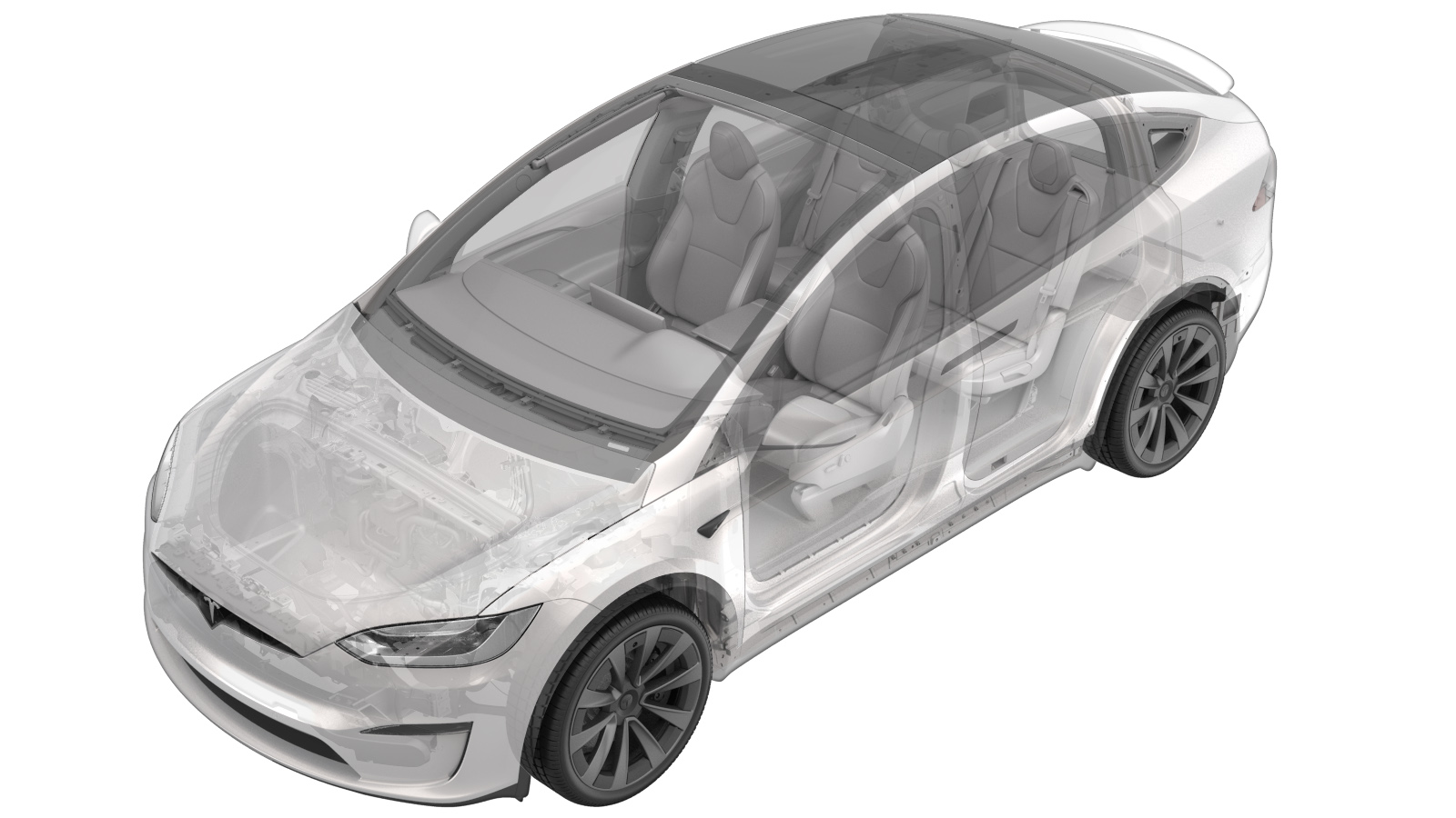
Sensor - HVAC - Windshield (Remove and Replace)
 Correction code
10206002
0.24
NOTE: Unless otherwise explicitly
stated in the procedure, the above correction code and FRT reflect all of the work
required to perform this procedure, including the linked procedures. Do not stack correction codes unless
explicitly told to do so.
NOTE: See Flat Rate Times to learn
more about FRTs and how they are created. To provide feedback on FRT values, email ServiceManualFeedback@tesla.com.
NOTE: See Personal Protection to make sure proper PPE is worn when
performing the below
procedure.
- 2024-12-02: Updated notes and Service Mode instructions.
Remove
- Remove the lower quad camera cover. See Camera Cover - Lower (Remove and Replace).
- Remove the rear view mirror. See Mirror - Rear View (Remove and Replace).
- Remove the upper quad camera cover. See Upper Cover - Rear View Mirror (Remove and Replace).
-
Disconnect the windshield HVAC sensor
electrical connector.
-
Remove and discard the screws (x2)
that attach the windshield HVAC sensor to the windshield bracket.
NotePH00 Philips. Torque 0.12 Nm.CAUTIONThe fasteners are tiny. Take care not to drop or misplace them. Make sure that the correct phillips screwdriver is used. If the screwdriver is too large, the screws will round out.
-
Remove the windshield HVAC sensor from
the windshield bracket.
NoteUse a pocket screwdriver to gently pry on sensor to release the foam from the adhesive.
Install
-
Clean the area where new windshield
HVAC sensor foam pad will rest into position.
CAUTIONMake sure all adhesive residue from the windshield is removed and the windshield is dry before installation. The foam pad will not stick if the windshield is wet. Align the located hole of the sensor with the plastic alignment pin on the windshield bracket.TIpUse of the following tool(s) is recommended:
- IPA wipes
NoteAllow 1 minute dry time before continuing. -
Install the windshield HVAC sensor on
the windshield bracket.
NoteAlign the hole on the PCB with the plastic alignment pin.
-
Install the new screws (x2) that
attach the windshield HVAC sensor to the windshield bracket.
CAUTIONMake sure that the screws are not over torqued as they are very delicate and will strip very easily.NotePH00 Philips. Torque 0.12 Nm.NoteInstall new screws.
-
Connect the windshield HVAC sensor
electrical connector.
- Install the upper quad camera cover. See Upper Cover - Rear View Mirror (Remove and Replace).
- Install the rear view mirror. See Mirror - Rear View (Remove and Replace).
- Install the lower quad camera cover. See Camera Cover - Lower (Remove and Replace).
-
Perform the following
routine using Service Mode or Toolbox (see 0005 - Service Modes):
UPDATE_CAN-REDEPLOYvia Toolbox: (link)via Service Mode Plus:
- Drive Inverter Replacement ➜ Drive Inverter DIRE1L Replacement ➜ CAN Redeploy
- Drive Inverter Replacement ➜ Drive Inverter DIRE1R Replacement ➜ CAN Redeploy
- Drive Inverter Replacement ➜ Drive Inverter DIRE2 Replacement ➜ CAN Redeploy
- Drive Inverter ➜ Front Drive Inverter Replacement ➜ CAN Redeploy
- Drive Inverter ➜ Rear Drive Inverter Replacement ➜ CAN Redeploy
- Drive Inverter ➜ Rear Left Drive Inverter Replacement ➜ CAN Redeploy
- Drive Inverter ➜ Rear Right Drive Inverter Replacement ➜ CAN Redeploy
- Drive Unit ➜ Front Drive Unit Replacement ➜ CAN Redeploy
- Drive Unit ➜ Rear Drive Unit Replacement ➜ CAN Redeploy
- Thermal ➜ HVAC ➜ CAN Redeploy
- chassis ➜ DPB Post Replacement ➜ CAN Redeploy
- chassis ➜ ESP Post Replacement ➜ CAN Redeploy
- chassis ➜ IDB Post Replacement ➜ CAN Redeploy
- chassis ➜ RCU Post Replacement ➜ CAN Redeploy
- chassis ➜ ESP Replacement Panel ➜ CAN Redeploy
- chassis ➜ IBST Replacement Panel ➜ CAN Redeploy