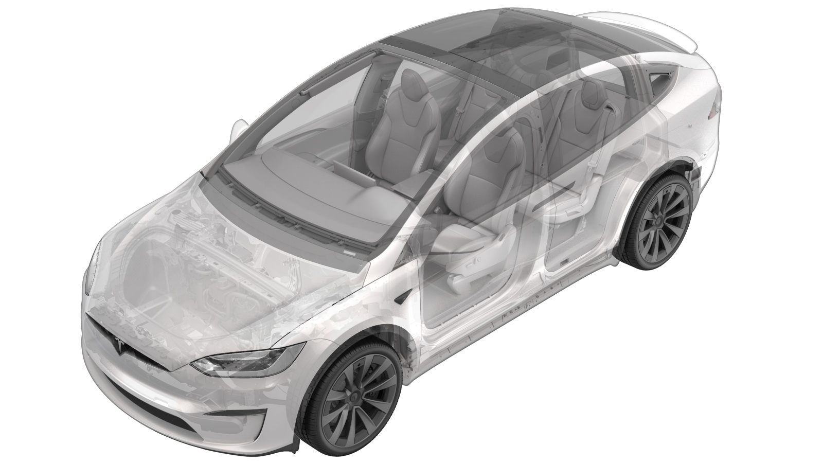
HV Harness - HV Battery to Rear Drive Unit - LH (Plaid) (Remove and Replace)
 Correction code
44500012
3.30
NOTE: Unless otherwise explicitly
stated in the procedure, the above correction code and FRT reflect all of the work
required to perform this procedure, including the linked procedures. Do not stack correction codes unless
explicitly told to do so.
NOTE: See Flat Rate Times to learn
more about FRTs and how they are created. To provide feedback on FRT values, email ServiceManualFeedback@tesla.com.
NOTE: See Personal Protection to make sure proper PPE is worn when
performing the below
procedure.
Remove
- Remove the rear subframe assembly (plaid). See Subframe Assembly - Rear (Plaid) (Remove and Install).
-
Release the clip that attaches the
rear drive unit ground strap to the rear subframe.
-
Remove the bolts (x2) that attach the
LH upper aft link to the rear subframe.
 85 Nm (62.7 lbs-ft)TIpUse of the following tool(s) is recommended:
- 16 mm deep socket
-
Remove the bolts (x2) that attach the
RH upper aft link to the rear subframe.
 85 Nm (62.7 lbs-ft)TIpUse of the following tool(s) is recommended:
- 16 mm deep socket
-
Remove the bolts (x4) that attach the
performance rear subframe brace.
 120 Nm (88.5 lbs-ft)TIpUse of the following tool(s) is recommended:
- 16 mm deep socket
-
Position the drive unit stand
underneath the gantry.
-
Release the clips (x4) that attach the
tail end of the LV harness.
-
Disconnect the rear electric oil feed
pump electrical connector.
NoteRelease the connector lock, press and gently pull the electrical connector.
-
Attach the hooks (x3) from the drive
unit sling tool to the drive unit.
NoteInstall additional shackle on both sides to alleviate the tension to the cables.
-
Secure the drive unit sling to the
gantry.
-
Raise the sling so there is slight
tension on the cables.
-
Remove the LH bolt that attaches the
rear drive unit to the rear subframe.
 120 Nm (88.5 lbs-ft)TIpUse of the following tool(s) is recommended:
- External Torx E18
-
Remove the RH bolt that attaches the
rear drive unit to the rear subframe.
 120 Nm (88.5 lbs-ft)TIpUse of the following tool(s) is recommended:
- External Torx E18
-
Loosen the bolt that attaches the rear
of rear drive unit to the rear subframe.
 120 Nm (88.5 lbs-ft)TIpUse of the following tool(s) is recommended:
- Torx T20 socket
NoteFull removal of the bolt is not required. -
Carefully raise the sling and
partially lift the rear drive unit upwards.
CAUTIONDo not stress and damage any related components.
-
Release the bolt that attaches the LH
HV harness to the rear drive unit.
 6 Nm (4.4 lbs-ft)TIpUse of the following tool(s) is recommended:
- 10 mm socket
-
Disconnect the LH HV harness
electrical connector from the LH rear inverter.
CAUTIONDisengage the locking tab, and then rotate the lever up to release the electrical connector. Do not force the release lever up.
-
Remove the LH HV harness from the rear
drive unit.
NoteFeed the HV harness out from under the rear drive unit.
Install
-
Install the LH HV harness to the rear
drive unit.
NoteFeed the HV harness onto the rear drive unit for installation.
-
Connect the LH HV harness electrical
connector to the LH rear inverter.
NoteVerify that the lever is in the upright and open position. Carefully seat the electrical connector and allow lever to engage. Fully secure the lever, and then engage the red locking tab.
-
Install the bolt that attaches the LH
HV harness to the rear drive unit.
 6 Nm (4.4 lbs-ft)TIpUse of the following tool(s) is recommended:
- 10 mm socket
-
Lower the sling, and then return the
rear drive unit into position.
-
Hand-tighten the RH bolt that attaches
the rear drive unit to the rear subframe.
NoteTorque at a later step.
-
Hand-tighten the LH bolt that attaches
the rear drive unit to rear subframe
NoteTorque at a later step.
-
Lower the sling to release the tension
on the cables.
-
Remove the drive unit sling from the
gantry.
-
Remove the drive unit sling hooks tool
(x3) from the rear drive unit.
-
Tighten the motor mount bolts
(x3).
TIpUse of the following tool(s) is recommended:
-
External
Torx E18
 120 Nm (88.5 lbs-ft)
 -
Torx T20 socket
 213 Nm (157.1 lbs-ft)
-
External
Torx E18
-
Connect the rear electric oil feed
pump electrical connector.
NoteEngage the connector lock, and then install and gently pull to test for a secure connection.
-
Fasten the clips (x4) that attach the
tail end of the LV harness.
- Install the rear subframe assembly (plaid). See Subframe Assembly - Rear (Plaid) (Remove and Install).