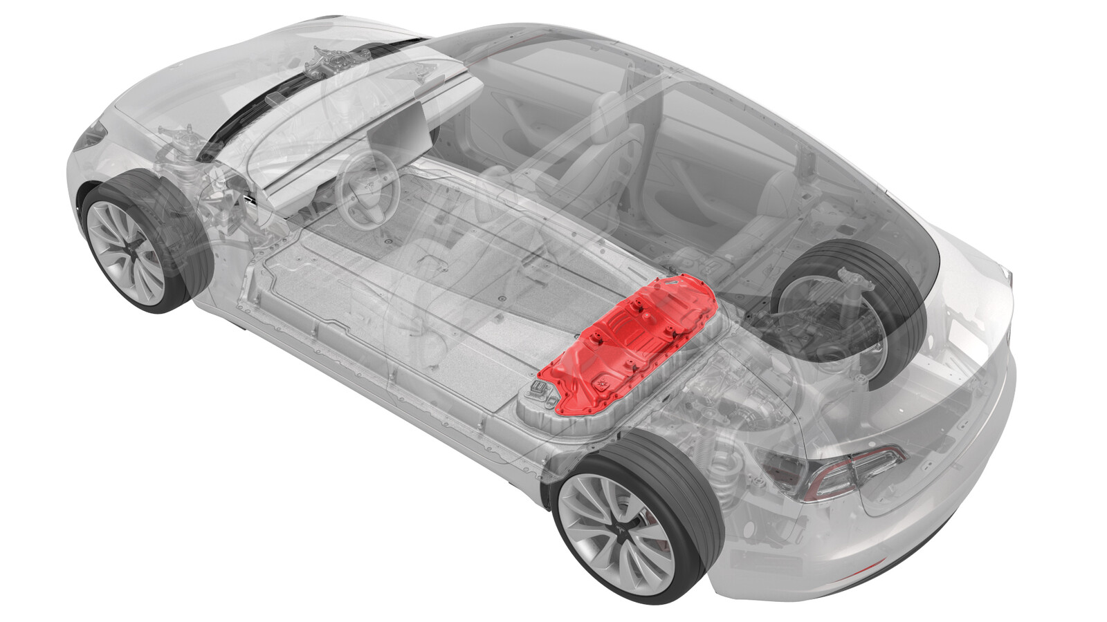
Cover - Ancillary Bay (Swap) (Battery On Table)
 Correction code
16300107
0.36
NOTE: Unless otherwise explicitly
stated in the procedure, the above correction code and FRT reflect all of the work
required to perform this procedure, including the linked procedures. Do not stack correction codes unless
explicitly told to do so.
NOTE: See Flat Rate
Times to learn more about FRTs and how they are created.
NOTE: See Personal Protection to make sure wearing proper PPE when
performing the below procedure. NOTE: See Ergonomic Precautions for safe and healthy working
practices.
Correction code
16300107
0.36
NOTE: Unless otherwise explicitly
stated in the procedure, the above correction code and FRT reflect all of the work
required to perform this procedure, including the linked procedures. Do not stack correction codes unless
explicitly told to do so.
NOTE: See Flat Rate
Times to learn more about FRTs and how they are created.
NOTE: See Personal Protection to make sure wearing proper PPE when
performing the below procedure. NOTE: See Ergonomic Precautions for safe and healthy working
practices.
Only
technicians who have completed all required certification courses are permitted to
perform this procedure. Tesla recommends third party service provider technicians
undergo equivalent training before performing this procedure. For more information on
Tesla Technician requirements, or descriptions of the subject matter for third parties,
see HV Certification Requirements. Proper personal protective equipment (PPE) and insulating HV
gloves with a minimum rating of class 0 (1000V) must
be worn at all times a high voltage cable, busbar, or fitting is handled. Refer to Tech Note TN-15-92-003, High Voltage Awareness
Care Points
for additional safety
information.
Torque Specifications
| Description | Torque Value | Recommended Tools | Reuse/Replace | Notes |
|---|---|---|---|---|
| Bolts that attach the ancillary bay rails to the body and ancillary bay cover |
 24 Nm (17.7 lbs-ft) |
|
Reuse | |
| Nut that attaches the positive 12V output cable to the DCDC passthrough |
9 Nm (6.6 lbs-ft) |
|
Replace | 1523698-00-A |
| Bolts that attach the ancillary bay cover to the high voltage controller |
5 Nm (3.7 lbs-ft) +30 deg |
|
Reuse | |
| Bolt attaches the ancillary bay cover to the HV battery |
8 Nm (5.9 lbs-ft) |
|
Reuse |
Remove
-
With the HV battery removed
from the vehicle, remove the bolts that attach the high voltage controller
internally to the ancillary bay cover.
TIpUse of the following tool(s) is recommended:
- External Torx E10
Figure 1. 4-Bolt HVC Ancillary Bay Cover Figure 2. 3-Bolt HVC Ancillary Bay Cover -
Put on HV insulating gloves
and leather over gloves.
WarningContinue to wear the gloves until instructed to remove them.
-
Loosen the bolts that attach
the ancillary bay cover to the HV battery.
CAUTIONUse an External Torx E10 5-Lobe socket that is not magnetized. Sockets with magnets will not fully grip and can possibly strip the bolt head.NoteThe bolts are captive to the ancillary bay cover.TIpUse of the following tool(s) is recommended:
- External Torx E10 5-Lobe
-
Remove the logic connector
cap from the high voltage controller connector.
-
Remove the ancillary bay
cover from the HV battery.
- Repeat steps 1 to 5 on the replacement HV battery.
Install
-
Visually inspect the
condition of the ancillary bay cover gasket and the new HV battery mating
surface for cracks, cuts, gouges, abrasions, or any damage that could affect
the seal.
NoteIf the damage to the gasket is severe, replace the ancillary bay cover gasket. If there is minor damage (including paint) that might affect the seal, perform an ancillary bay air leak test when instructed to do so.
- Use an IPA wipe to clean any residue from the high voltage controller mounting bolt holes and both the inside and outside of the ancillary bay cover at the bolt holes.
-
Install the ancillary bay
cover on the new HV battery, and then hand-tighten the bolts.
NoteDifferent ancillary bay cover revisions have 28, 18, or 16 bolts.
- Remove HV insulating gloves.
-
Reinstall the logic
connector cap onto the high voltage controller connector.
-
Torque the ancillary bay
cover bolts in the sequence shown, and mark each with an orange paint pen as
they are torqued.8 Nm (5.9 lbs-ft)CAUTIONUse an External Torx E10 5-Lobe socket that is not magnetized. Sockets with magnets will not fully grip and can possibly strip the bolt head.TIpUse of the following tool(s) is recommended:
- External Torx E10 5-Lobe
Figure 3. 28-Bolt Ancillary Bay Cover Torque Sequence Figure 4. 18-Bolt Ancillary Bay Cover Torque Sequence Figure 5. 16-Bolt Ancillary Bay Cover Torque Sequence -
Install and hand-tighten the
bolts that attach the high voltage controller internally to the ancillary
bay cover.
CAUTIONDo not remove the LH upper A-pillar trim tether from the body side. If removed from the body side, the tether will have to be replaced.
Figure 6. 5-Bolt HVC Ancillary Bay Cover Figure 7. 4-Bolt HVC Ancillary Bay Cover Figure 8. 3-Bolt HVC Ancillary Bay Cover -
Torque the high voltage
controller to ancillary bay cover bolts in the sequence shown, and mark each
bolt with an orange paint pen as they are torqued.
 5 Nm (3.7 lbs-ft) +30 degCAUTIONInsufficient torque of bolts 1 and 2 opens the high voltage interlock loop circuit.TIpUse of the following tool(s) is recommended:
- External Torx E10
Figure 9. 5-Bolt HVC Ancillary Bay Cover Figure 10. 4-Bolt HVC Ancillary Bay Cover Figure 11. 3-Bolt HVC Ancillary Bay Cover - Repeat steps 2 to 8 on the old HV battery to be shipped.
-
If damage was found on the
ancillary bay cover gasket or the HV battery mating surface, or if the
aluminum tape retrofit patch was replaced, or if another procedure
instructed to perform an ancillary bay air leak test, do that now. See Ancillary Bay Air Leak Test (Inspection).
NoteIf an ancillary bay air leak test is performed, add correction code 16100400 as a separate activity to the Service Visit.