Steering Column (RHD) (Remove and Replace)
 Correction code
32051912
1.08
NOTE: Unless otherwise explicitly
stated in the procedure, the above correction code and FRT reflect all of the work
required to perform this procedure, including the linked procedures. Do not stack correction codes unless
explicitly told to do so.
NOTE: See Flat Rate
Times to learn more about FRTs and how they are created.
NOTE: See Personal Protection to make sure wearing proper PPE when
performing the below procedure. NOTE: See Ergonomic Precautions for safe and healthy working
practices.
Correction code
32051912
1.08
NOTE: Unless otherwise explicitly
stated in the procedure, the above correction code and FRT reflect all of the work
required to perform this procedure, including the linked procedures. Do not stack correction codes unless
explicitly told to do so.
NOTE: See Flat Rate
Times to learn more about FRTs and how they are created.
NOTE: See Personal Protection to make sure wearing proper PPE when
performing the below procedure. NOTE: See Ergonomic Precautions for safe and healthy working
practices.
- 2025-06-05: Added step to reconnect 12V/LV power.
- 2025-04-04: Updated configuration instructions.
- 2024-12-02: Modified steering column configuration and calibration steps.
- 2024-10-25: Added step to transfer clip from old column to new column.
- 2023-11-09: Added installation sequence with updated steering column gateway configuration steps.
Torque Specifications
| Description | Torque Value | Recommended Tools | Reuse/Replace | Notes |
|---|---|---|---|---|
| Bolt that attaches the steering column intermediate shaft to the steering gear input shaft |
 18 Nm (13.3 lbs-ft) |
|
Replace | |
| Nut that attaches the steering column to the cross car beam |
 15 Nm (11.1 lbs-ft) |
|
Reuse |
Remove
- Open both front doors and lower the windows.
- From the touchscreen, move the steering column to the lowest and most outward position.
- Set the steering wheel straight ahead.
- Move the RH front seat backward and recline the seatback.
- Disconnect 12V/LV power. See 12V/LV Power (Disconnect and Connect).
- Remove the underhood storage unit. See Underhood Storage Unit (Remove and Replace).
-
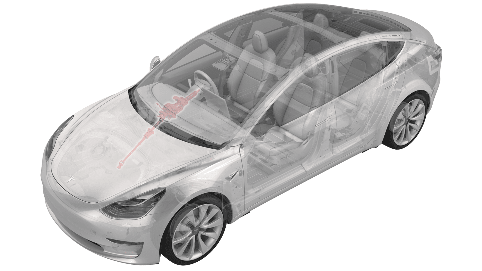
Remove the bolt that
attaches the intermediate shaft to the steering rack assembly, and then
slide the intermediate shaft upwards to remove it from the steering
rack.
TIpUse of the following tool(s) is recommended:
- 13 mm socket
- Ratchet/torque wrench
Figure 1. LHD shown, RHD similar - Remove the LH and RH mid A-pillar trim. See Trim - A-Pillar - Middle - LH (Remove and Replace).
- Remove the RH footwell cover. See Cover - Footwell - Driver (Remove and Replace).
- Remove the RH footwell vent duct. See Duct - Footwell - RH (RHD) (Remove and Replace).
- Remove the main instrument panel decor trim. See Decor Trim - Instrument Panel - Main (Remove and Replace).
- Remove the steering wheel. See Steering Wheel (Remove and Install).
- Remove the steering column control module. See Module - Steering Column Control (Remove and Replace).
- Remove the screws (x2) that attach the IP carrier to the cross car beam on the lower RH side.
- Remove the lower gap hider. See Gap Hider - Steering Column - Lower (Remove and Replace).
- Apply tape to the instrument panel area around the steering column to protect it from damaging.
- Disconnect the instrument panel harness connector from the steering column.
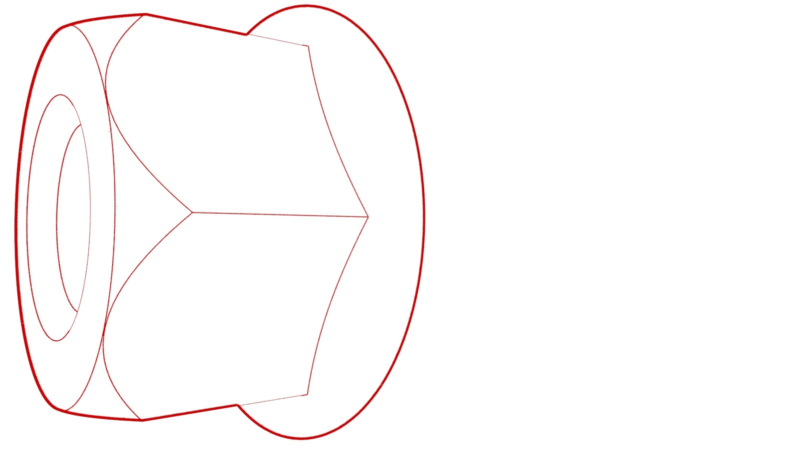
-
Remove the nuts (x4) that attach the
steering column to the cross car beam.
TIpUse of the following tool(s) is recommended:
- 13 mm socket
- 3 in extension
- Flex head ratchet/flex head torque wrench
Figure 2. LHD shown, RHD similar -
Remove the steering column assembly from the vehicle:
- Slowly pull the assembly inwards,tilting the upper portion of the steering column towards the roof of the vehicle to clear it from the instrument panel.
- Once the motor contacts the cross beam, slightly pull on the lower IP area below the assembly to allow the motor to clear the cross beam. Rotate the assembly to the right to clear the bottom left portion of the motor, and then remove the assembly from the vehicle.
Install
- Record the part number of the replacement steering column to be used later in the procedure when the gateway configuration is set.
-
Transfer the steering column clip (PN: 1099272-00-E) from the old steering column to
the replacement steering column.
- With the help of an assistant, carefully move the intermediate shaft of the steering column through the opening in the instrument panel carrier, rotate the steering column to the right so that the rear motor lower portion clears the instrument panel carrier opening, and then rotate left.
-
Install the steering column to the
cross car beam, and then install the nuts (x4) that attach the steering column to the
cross car beam.15 Nm (11.1 lbs-ft)TIpUse of the following tool(s) is recommended:
- 13 mm socket
- 3 in extension
- Flex head ratchet/flex head torque wrench
Figure 3. LHD shown, RHD similar - Connect the instrument panel harness to the steering column connector.
- Remove the tape from the instrument panel.
- Install the lower gap hider. See Gap Hider - Steering Column - Lower (Remove and Replace).
-
Install the screws (x2) that attach
the IP carrier to the cross car beam on the lower RH side.
 2.3 Nm (1.7 lbs-ft)
 - Install the steering column control module. See Module - Steering Column Control (Remove and Replace).
- Install the steering wheel. See Steering Wheel (Remove and Install).
- Install the main instrument panel decor trim. See Decor Trim - Instrument Panel - Main (Remove and Replace).
- Install the RH footwell vent duct. See Duct - Footwell - RH (RHD) (Remove and Replace).
- Install the RH footwell cover. See Cover - Footwell - Driver (Remove and Replace).
- Connect 12V/LV power. See 12V/LV Power (Disconnect and Connect).
- Install the LH and RH mid A-pillar trim. See Trim - A-Pillar - Middle - LH (Remove and Replace).
-
Slide the intermediate shaft downward
to install it onto the steering rack shaft, and then install the bolt that attaches the
shaft to the rack.18 Nm (13.3 lbs-ft)TIpUse of the following tool(s) is recommended:
- 13 mm socket
- Ratchet/torque wrench
Figure 4. LHD shown, RHD similar - Install the underhood storage unit. See Underhood Storage Unit (Remove and Replace).
- Connect a laptop with Toolbox to the vehicle. See Toolbox (Connect and Disconnect).
-
Use the replacement steering column
part number recorded earlier and this table to determine the type of steering column
installed and configuration value to be chosen.
Part Number Drive Build Location Configuration Value 1044811 LHD Fremont and early Giga Shanghai "BOSCH" 1044816 RHD Fremont and early Giga Shanghai "BOSCH" 1044871 LHD Giga Shanghai "JE" 1044876 RHD Giga Shanghai "JE" - In Toolbox, click , click the Vehicle Configuration tab, scroll to steeringColumnMotorType, from the drop down menu to the right, select the value according to the above table, and then click Apply Changes.
- Perform the following routine using Service Mode or Toolbox (see 0005 - Service Modes): PROC_STEERING_COLUMN_CALIBRATIONvia Service Mode:Chassis ➜ Steering ➜ Calibrate Steering Columnvia Toolbox:(link)
- Disconnect the laptop with Toolbox from the vehicle. See Toolbox (Connect and Disconnect).
- Restore the driver and front passenger seats back to their original position.
- Restore the steering column back to its original position.
- Raise both front windows and close both front doors.