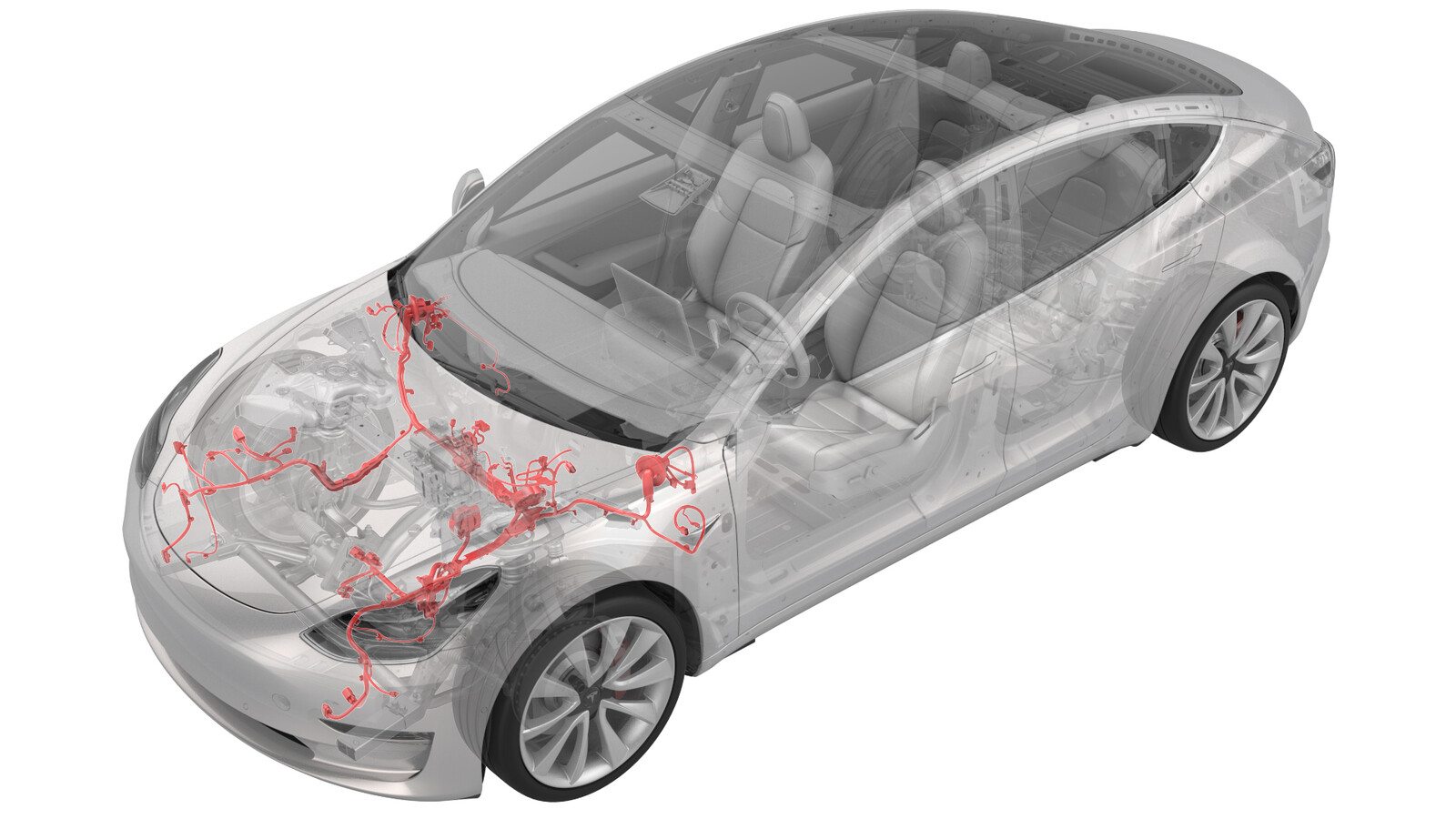
Harness - Main Front (LHD) (Remove and Replace)
 Correction code
17100702
4.02
NOTE: Unless otherwise explicitly
stated in the procedure, the above correction code and FRT reflect all of the work
required to perform this procedure, including the linked procedures. Do not stack correction codes unless
explicitly told to do so.
NOTE: See Flat Rate
Times to learn more about FRTs and how they are created.
NOTE: See Personal Protection to make sure wearing proper PPE when
performing the below procedure. NOTE: See Ergonomic Precautions for safe and healthy working
practices.
Correction code
17100702
4.02
NOTE: Unless otherwise explicitly
stated in the procedure, the above correction code and FRT reflect all of the work
required to perform this procedure, including the linked procedures. Do not stack correction codes unless
explicitly told to do so.
NOTE: See Flat Rate
Times to learn more about FRTs and how they are created.
NOTE: See Personal Protection to make sure wearing proper PPE when
performing the below procedure. NOTE: See Ergonomic Precautions for safe and healthy working
practices.
- 2025-04-29: Corrected torque figures for the bolts that attach the shock tower brace to the vehicle.
- 2023-08-25: Updated EPB Service Mode reference.
- 2023-06-21: Added note to check brake pedal feel and bleed brakes if needed.
- 2023-03-21:Revised procedure
Remove
- Open all four doors and lower all four windows.
- Enable the EPB Service Mode. See Parking Brake - Caliper - Rear - LH (Release)
-
Move LH front seat
forward
-
Move RH front seat
forward
-
Remove 2nd row seat cushion
and disconnect harness
Note2x tabs, 2x connectors, Slide locking tabs to left of vehicle while lifting up seat bench. Newer models have connectors on both sides of bench, Older models have 2x connectors on one side of bench
-
Move LH front seat
backward
-
Move RH front seat
backward
-
Open hood
NotePress "Open" button on the touchscreen to release the latch, Lift the lid manually
-
Remove rear apron
Note12x clips, Only store rear apron visible face upwards
-
Power off vehicle from
center display
NoteVia Controls > Safety > Power Off, Select Power Off button at warning dialogue box
-
Disconnect 12V negative
terminal
Note1x nut, 10mm, 6 Nm, Ensure the vehicle is in park, climate control system is off, and vehicle is not charging before disconnecting 12V
-
Remove 12V cap from
ancillary bay
Note1x cap
-
Disconnect HVC logic
connector and install logic cap
Note1x connector, 1x cap, Release locking tab then push the handle downward to release connector
-
Remove LH IP end cap
Note3x clips
-
Remove LH air wave bezel cap
from main decor assembly
Note2x clips
-
Remove LH mid A-pillar
assembly
Note1x clip, 1x tab, Release the upper clip then pull mid A-pillar upward to remove
-
Remove clip for LH lower
A-pillar trim
Note1x push clip
-
Remove LH lower A-pillar
trim
Note2x clips, 3 guide tabs, Pull rear of lower A-pillar upward to release clip then pull rearward to release front tabs from carpet
-
Remove screw and clips
securing LH footwell cover
Note2x push clips, 1x screw, T20, 2.5 Nm
-
Remove connectors from LH
footwell cover and remove from vehicle
Note3x tabs, 1x Ethernet connector, 1x puddle light connector, APAC specific vehicles have an additional OBDII connector that will have to be disconnected
-
Remove fasteners securing
driver knee air bag to vehicle
Note1x push clip, 2x screws, T20, 2 Nm, 4x patch bolts, T30, 8 Nm, Newer vehicles have 4x patch bolts, E10, Discard after removal, Support the knee air bag while lowering, The connector / harness length is very short
-
Disconnect the driver knee
air bag and remove from vehicle
Note1x connector, Release locking tabs, Then release squib from air bag, Support air bag while disconnecting, Connector release may vary
-
Remove RH IP end cap
Note3x clips
-
Remove RH air wave bezel cap
from main decor assembly
Note2x clips
-
Remove RH mid A-pillar
assembly
Note1x clip, 1x tab, Release upper clip then pull mid A-pillar upward to remove from vehicle
-
Remove clip for RH lower
A-pillar trim
Note1x push clip
-
Remove RH lower A-pillar
trim
Note1x clip, 2 guide tabs, Pull rear of lower A-pillar upward to release clip then pull rearward to release front tabs from carpet
-
Release RH footwell assembly
from IP
Note4x push clips
-
Remove RH footwell
assembly
Note2x connectors
-
Remove the fasteners
securing passenger knee airbag to vehicle
Note4x patch bolts, T30, 8 Nm, Discard after removal, 2x screws, T20, 2 Nm, Newer vehicles have 4x patch bolts, E10, Discard after removal, Support the knee air bag while lowering, The connector / harness length is very short
-
Remove passenger knee air
bag from vehicle
Note1x connector, Release locking tab, Connector release may vary
-
Remove main decor
assembly
Note15x clips, Entire decor does not need to come off for glove box removal, If you lift RH side of decor then you will have access to 3x torx screws securing top of glove box, Replace securing clips as needed
-
Remove screws securing glove
box assembly to IP carrier
Note6x screws, T20, 2.3 Nm
-
Disconnect glove box
assembly connectors
Note3x electrical connectors
-
Remove glove box from IP
carrier
Note3x clips
-
Remove passenger footwell
air duct
Note1x push clip
-
Remove RH IP air wave
duct
Note2x push clips
-
Remove clips securing RH
front main cabin carpet to footwell area
Note3x push clips, Number of clips may vary on older vehicles
-
Fold RH front main cabin
carpet aside for access
Note2x clips, Lift center piece and pull carpet back, Release seat harness from clips to allow carpet to fold back more
-
Remove nuts securing RH
carpet locator bracket
Note2x nuts, 10mm, 2.5 Nm, Newer vehicles may use clips instead of nuts
-
Remove RH carpet locator
bracket from vehicle
-
Remove cabin intake upper
duct assembly
Note4x clips, Heat pump vehicles have 3x clips
-
Remove closeout panel from
frunk assembly
Note4x clips, 1x connector, Frunk safety switch, 3x guide tabs, Grab closeout panel from bottom then pull it upward to release clips, Disconnect the switch
-
Remove frunk assembly
carpet
-
Remove bolts securing frunk
assembly
Note7x bolts, 10mm, 5 Nm, Lift up RBN covers to access upper fasteners, Newer vehicles may not be equipped with covers
-
Remove frunk assembly from
vehicle
Note12x clips, Replace any clips if broken or missing, Number of clips may vary on older vehicles
-
Release the terminal cover
and remove the positive terminal
Note1x nut, 10mm, 6 Nm, 1x cover
-
Loosen the nut securing the
12V battery upper tie down bracket to the 12V battery strap assembly
Note1x nut, 10mm, 5 Nm
-
Push down and slide battery
strap assembly to the right to release from front hook and rear tie down
assembly
-
Remove the vent tube hose
from the LH side of 12V battery
Note1x hose
-
Remove 12V battery from
vehicle
-
Remove LH wiper arm nut
cover
Note1x cover
-
Disconnect washer hose from
LH wiper arm to Y-tube fitting and release washer hose clips
Note2x clips, 1x hose
-
Remove the nut securing the
LH wiper arm to wiper module
Note1x nut, 15mm, 25 Nm
-
Remove LH wiper arm and hose
assembly from vehicle
-
Remove RH wiper arm nut
cover
Note1x cover
-
Disconnect washer hose from
RH wiper arm to Y-tube fitting and release washer hose clips
Note2x clips, 1x hose
-
Remove the nut securing the
RH wiper arm to wiper module
Note1x nut, 15mm, 25 Nm
-
Remove RH wiper arm and hose
assembly from vehicle
-
Remove the LH shock tower
cover
Note2x push clips
-
Remove the RH shock tower
cover
Note2x push clips
-
Release cowl screen from
windshield and remove from vehicle
Note2x push clips, 6x clips
-
Remove 12V battery rear hook
tie down assembly
Note1x bolt, T25, 9 Nm
-
Remove nuts securing
superbottle to shock tower brace assembly
Note2x nuts, 10mm, 8 Nm
-
Remove bolts securing
battery bracket to Shock Tower Brace Assembly
Note2x bolts, 13mm, 15 Nm
-
Remove coolant hose clip
from 12V battery bracket
Note1x fir tree clip
-
Remove the 12V battery drain
tube clip from the 12V battery bracket
Note1x edge clip
-
Remove the inner bolts that attach the
shock tower brace to the RH shock tower.
-
Remove the outer bolt that attaches
the shock tower brace to the RH shock tower.
-
Remove the inner bolts that attach the
shock tower brace to the LH shock tower.
-
Remove the outer bolt that attaches
the shock tower brace to the LH shock tower.
-
Shift shock tower brace
assembly to gain clearance
NoteShift shock tower brace forward, but do not fully remove
-
Remove the bolt securing
thermal sub-harness cover to front controller
Note1x bolt, 10mm, 6 Nm
-
Release the thermal
sub-harness cover tabs from front controller cover and remove from
vehicle
Note2x tabs
-
Disconnect thermal
sub-harness from front controller
Note1x connector
-
Release dual omega clip from
suction/liquid lines near TXV
NoteMove harness aside to gain clearance
-
Remove bolts securing front
controller shield assembly and remove from vehicle
Note9x bolts, E8, 6 Nm
-
Remove bolts securing front
controller
Note3x bolts, 10mm, 10 Nm
-
Disconnect front controller
harness connectors
Note4x connectors
-
Remove nyloc nuts and bolt
securing straps to front controller
Note6x nyloc nuts, 10mm, 8.5 Nm, 1x bolt, 10mm, 8.5 Nm, Discard after removal
-
Release clips from the
bottom of front controller assembly and remove lower busbar from stud
Note2x fir tree clips, 1x bus bar
-
Remove upper ground strap
from the vehicle body
Note1x bolt, 10mm, 9 Nm
-
Remove the ground bolt from
lower right side of front controller
Note1x bolt, 10mm, 9 Nm
-
Remove ground bolt from
lower rear of front controller
Note1x bolt, 10mm, 9 Nm
-
Remove the front controller
from vehicle
-
Release clips securing
coolant hoses and harnesses to 12V battery beam
Note4x fir tree clips
-
Remove bolts securing 12V
battery beam
Note2x bolts, 10mm, 9 Nm
-
Rotate the beam to gain
access to the clip on the left, underside of the 12V beam and remove the
clip
Note1x fir tree clip
-
Remove the 12V battery beam
with 12V battery bracket attached from vehicle
NoteThe beam will need to be slid to the right of the vehicle, Then the left side of the beam will need to be lifted, The beam will be removed at an angle from the left side of the vehicle
-
Disconnect wiper module
harness
Note1x connector, Do NOT place limbs within the linkage movement area as wiper arms will automatically transition to parking mode
-
Remove the bolts securing
wiper module
Note3x bolts, 10mm, 7 Nm
-
Remove wiper module from
vehicle
-
Remove HVAC plenum outer
duct
Note2x clips
-
Remove HVAC plenum inner
duct
Note4x clips
-
Remove and discard nuts
securing car computer to the bulkhead
Note4x nyloc nuts, 13mm, 7.1 Nm
-
Remove 12V positive cable
from right body controller
Note1x nyloc nut, 10mm, 8.5 Nm, 1x cable, Discard after removal
-
Disconnect DCDC positive
cable from right body harness
Note1x connector, Pull up the red locking tab and then press
-
Disconnect the connector
from the right body harness
Note1x connector
-
Disconnect frunk connector
from right controller
Note1x connector, J8
-
Slide car computer inward to
allow access to connectors and harness clips
NoteBe careful not to strain harness and connectors
-
Remove the front harness
clips from car computer
Note2x clips
-
Disconnect the LH front
harness connector from car computer
Note1x connector
-
Disconnect the RH front
harness connectors from car computer
Note5x connectors
-
Push the RH side of the
front harness through the bulkhead
Note4x clips
-
Disconnect windshield heater
connector
Note1x connector
-
Secure heater harness onto
windshield
-
Remove the front end harness
windshield connector from the body
Note1x clip
-
Release clips securing
harness behind RH shock tower
Note2x clips
-
Remove the 12V power cable
from left body controller
Note1x nyloc nut, 10mm, 8.5 Nm, Discard nyloc nut
-
Disconnect front harness
white connector X909 from LH body harness and separate from left body
controller
Note1x connector, 1x clip
-
Disconnect frunk connector
from left body controller
Note1x connector, J8
-
Push the LH side of the
front harness through the bulkhead
Note4x clips
-
Remove front harness clip
from washer tank
Note1x clip
-
Disconnect front harness
connectors from brake booster area
Note3x connectors, Washer tank, Brake fluid level sensor, Brake booster
-
Disconnect brake booster
lower connector
Note1x connector
-
Disconnect the hydraulic
control unit connector
Note1x connector, Disengage locking tab and pull up on connector to release
-
Remove nuts securing brake
master cylinder to brake booster
Note2x nuts, 13mm, 20 Nm
-
Release brake master
cylinder from ibooster and move aside
-
Remove O-ring from brake
master cylinder
Note1x O-ring, discard after removal
-
Remove front harness clips
around LH front frame rail area
Note5x clips
-
Remove front harness clips
around LH headlamp area
Note2x clips
-
Remove the front harness
ground terminals at LH front shock tower
Note2x bolts, 10mm, 8 Nm, Inspect bolts: if they are self tapping tri-lobular bolts (1128269-00-A) then discard, If they are normal bolts (1447438-00-A) they can be reused
-
Remove the LH front harness
test junction
Note1x bolt, 10mm, 8 Nm, Inspect bolt: if it is a self tapping tri-lobular bolt (1128269-00-A) then discard, If it is a normal bolt (1447438-00-A) it can be reused
-
Remove the front harness
ground terminal in the LH headlamp area
Note1x bolt, 10mm, 8 Nm, Inspect bolt: if it is a self tapping tri-lobular bolt (1128269-00-A) then discard, If it is a normal bolt (1447438-00-A) it can be reused
-
Disconnect the steering gear
assembly connectors
Note2x connectors, Two stage connectors, Move the red locking tab to the left then depress the connector release to disconnect the connector
-
Disconnect the logic
connectors at the steering gear area
Note2x connectors, Two stage connectors, Slide the grey locking tab away from the connector and depress the grey tab to disconnect the connector
-
Release connection for the
FDU front subframe harness
Note1x locking connector, Release the grey locking tab then press on the tab to release the connector
-
Disconnect LH front
headlamp
Note1x connector, Pull tab to disengage lock mechanism, Pull again to release connector, Do not press down on tab, Connector style may vary
-
Disconnect the TXV
connector
Note1x connector
-
Remove the front harness
clip around RH front frame rail area
Note1x clip
-
Remove the front harness
clips around the RH headlamp area
Note2x clips
-
Remove the front harness
test junction around RH front frame rail area
Note1x bolt, 10mm, 8 Nm, Inspect bolt: if it is a self tapping tri-lobular bolt (1128269-00-A) then discard, If it is a normal bolt (1447438-00-A) it can be reused
-
Disconnect RH headlamp
connector
Note1x connector
-
Push vehicle onto lift
NoteRecommend assistance, Note this vehicle can only be safely pushed for a very short distance and at very slow speed
-
Raise and support
vehicle
-
Remove LH front wheel center
cap
Note1x cap
-
Remove RH front wheel center
cap
Note1x cap
-
Loosen LH front wheel
Note5x nuts, 21mm, 175 Nm
-
Loosen RH front wheel
Note5x nuts, 21mm, 175 Nm
-
Raise vehicle partially and
lower lift onto locks
NoteSet vehicle to a comfortable working height, Make sure there's an audible click of the locks on both sides before lowering, otherwise vehicle may tilt to the side
-
Remove LH front wheel
Note5x nuts, 21mm, 175 Nm
-
Remove bolt securing LH
front wheel liner to body
Note1x bolt, 10mm, 5 Nm
-
Remove push clips securing
LH front wheel liner
Note16x push clips, The number of clips on newer vehicles may vary
-
Remove stud retaining clips
securing RH front wheel liner
Note2x clips, The number of clips on newer vehicles may vary
-
Remove LH front wheel liner
from vehicle
-
Remove lower bolt securing
washer tank to vehicle
Note1x bolt, 10mm, 3 Nm
-
Remove RH front wheel
Note5x nuts, 21mm, 175 Nm
-
Remove bolt securing RH
front wheel liner to body
Note1x bolt, 10mm, 5 Nm
-
Remove push clips securing
RH front wheel liner
Note16x push clips, The number of clips on newer vehicles may vary
-
Remove stud retaining clips
securing RH front wheel liner
Note2x clips, The number of clips on newer vehicles may vary
-
Remove RH front wheel liner
from vehicle
-
Disconnect 12V harness for
front fascia
Note1x locking connector, Release the locking tab by sliding it away from the connector, Then depress the grey lock to release the connector
-
Remove front harness clip
from the RH front fascia mounting bracket
Note1x clip
-
Disconnect front harness
from front end module harness
Note1x locking connector
-
Disconnect the front harness
from the RH acceleration sensor
Note1x locking connector
-
Remove the front harness
clips from the outer RH rail area
Note2x clips
-
Disconnect the RH front
wheel speed sensor
Note1x connector
-
Remove the front harness
clips around front of RH front wheel liner for the wheel speed sensor
Note2x clips
-
Remove the front harness
clip at the rear of RH front wheel liner area for the side repeater and
camera harness
Note1x clip
-
Disconnect the front harness
connectors for the RH side repeater and camera
Note2x connectors
-
Disconnect the front harness
connector for the LH front carrier harness
Note1x locking connector
-
Disconnect the front harness
from the LH acceleration sensor
Note1x locking connector
-
Remove the front harness
clips from the outer LH rail area
Note2x clips
-
Disconnect the front harness
from CFM
Note1x connector
-
Disconnect the LH front
wheel speed sensor
Note1x connector
-
Remove the front harness
clips around LH front wheel liner area
Note3x clips, North American region vehicles have 2x clips
-
Remove the front harness
clip for the LH side repeater and camera harness
Note1x clip
-
Disconnect the front harness
connectors for the LH side repeater and camera
Note2x connectors
-
Raise vehicle fully and
lower lift onto locks
NoteSet vehicle to comfortable working height, Make sure there's an audible click of the locks on both sides before lowering, otherwise vehicle may tilt to the side, Verify doors are clear of surrounding objects
-
Remove outer fasteners
securing front aero shield
Note9x bolts, 10mm, 5 Nm
-
Remove remaining nuts and
remove front aero shield from vehicle
Note2x nuts, 15mm, 5 Nm
-
Remove the front harness
clips around the bulkhead area
Note3x clips
-
Release HV harness bracket
from bulkhead
Note2x clips
-
Disconnect the front harness
HVIL connectors
Note2x connectors
-
Lower vehicle to comfortable
working level
NoteRaise lift off locks, then hold lock release lever to keep locks free while vehicle is lowered, Set vehicle to comfortable working height
-
Remove upper bolt securing
washer tank to vehicle
Note1x bolt, 10mm, 3 Nm
-
Remove washer tank from
vehicle
Note2x connectors,Keep washer tank upright to keep contents from spilling
-
Remove the front harness
clips from the body under the washer tank area
Note4x clips
-
Remove the front harness
clips around LH frame rail area
Note3x clips
-
Remove the front harness
clips around RH frame rail area
Note3x clips
-
Route the LH side of the
front harness from wheel liner to frunk area
-
Route the LH side of the
front harness toward the front controller area
-
Route the RH side of the
front harness from wheel liner to frunk area
-
Route the RH side of the
front harness toward the front controller area
-
Remove the front harness
from vehicle
Install
-
Position the front harness
to vehicle for installation
NoteMake sure to route RH branch underneath A/C compressor HV harness
-
Route the front harness
around the brake booster area and push the LH side of the harness into
driver side compartment
Note4x clips, Make sure to install grommet in proper orientation
-
Route the front harness
around the HVAC plenum duct area and push the RH side of the harness into
passenger side compartment
Note4x clips, Route harness underneath A/C HV harness, Make sure to install grommet in proper orientation
-
Route the RH side of the
front harness toward the RH side of the front fascia area
NoteMake sure plastic housing is properly oriented with clips facing frame rail, Feed harness down behind fascia
-
Route the RH side of the
front harness from frunk to RH wheel liner area
-
Route HVIL connectors down
along bulkhead
-
Route the LH side of the
front harness toward the LH side front fascia area
NoteMake sure plastic housing is properly oriented with clips facing frame rail, Feed harness down behind fascia
-
Route the LH side of the
front harness from frunk to LH wheel liner area
-
Install the front harness
clips around LH frame rail area
Note3x clips, Number of clips may vary on newer vehicles
-
Install the front harness
clips around the RH front frame rail area
Note3x clips, Number of clips on new vehicles may vary
-
Install front harness clips
under the washer tank area
Note4x clips
-
Install washer tank into
vehicle
Note2x connectors
-
Install upper bolt securing
washer tank to vehicle
Note1x bolt, 10mm, 3 Nm
-
Raise vehicle fully and
lower lift onto locks
NoteSet vehicle to comfortable working height, Make sure there's an audible click of the locks on both sides before lowering, otherwise vehicle may tilt to the side
-
Connect the front harness
HVIL connectors
Note2x connectors
-
Secure HV harness bracket to
bulkhead
Note2x clips
-
Install the front harness
clips around the bulkhead area for the two HVIL harnesses
Note3x clips
-
Position front aero shield
to vehicle and install nuts
Note2x nuts, 15mm, 5 Nm
-
Apply Loctite 222 onto front
aero shield bolts and install outer fasteners to front aero shield
Note9x bolts, 10mm, 5 Nm
-
Lower vehicle partially and
set onto locks
NoteRaise lift off locks, then hold lock release lever to keep locks free while vehicle is lowered, Set vehicle to comfortable working height
-
Install lower bolt securing
washer tank to vehicle
Note1x bolt, 10mm, 3 Nm
-
Connect the front harness
connectors for the LH side repeater and camera
Note2x connectors
-
Install the front harness
clip around rear of LH front wheel liner area for the side repeater and
camera
Note1x clip
-
Install the front harness
clips around front of LH front wheel liner area for the wheel speed
sensor
Note3x clips, Vehicles not equipped with ride-height sensor have 2x clips
-
Connect the LH front wheel
speed sensor connector
Note1x connector
-
Install the harness clips at
outer side of LH rail
Note2x clips
-
Connect LH acceleration
sensor
Note1x connector
-
Connect the front harness
connector for the LH front end module harness
Note1x locking connector
-
Connect the front harness to
the CFM
Note1x connector
-
Connect the front harness
connectors for the RH side repeater and the camera
Note2x connectors
-
Install the front harness
clip around rear of RH front wheel liner area
Note1x clip
-
Install the front harness
clips around front of RH front wheel liner area
Note2x clips
-
Connect the RH front wheel
speed sensor harness connector
Note1x connector
-
Install the harness clips at
outer side of RH rail
Note2x clips
-
Connect RH front
acceleration sensor
Note1x locking connector
-
Connect the front harness
connector for the RH front carrier harness
Note1x locking connector, Engage locking tab
-
Install front harness clip
to the RH front fascia mounting bracket
Note1x clip
-
Secure 12V harness for front
fascia
Note1x connector, Engage the locking tab
-
Install RH front wheel
liner
-
Install the stud retaining
clips for RH front wheel liner
Note2x clips, The number of clips on newer vehicles may vary
-
Install the push clips for
the RH front wheel liner
Note16x push clips, The number of clips on newer vehicles may vary
-
Install bolt securing RH
front wheel liner to body
Note1x bolt, 10mm, 5 Nm
-
Install RH front wheel
Note5x nuts, 21mm, 175 Nm, Start lug nuts by hand before using power tool, Torque at later step
-
Position LH front wheel
liner to vehicle for installation
-
Install the stud retaining
clips for RH front wheel liner
Note2x clips, The number of clips on newer vehicles may vary
-
Install the push clips for
the LH front wheel liner
Note16x push clips, The number of clips on newer vehicles may vary
-
Install bolt securing LH
front wheel liner to body
Note1x bolt, 10mm, 5 Nm
-
Install LH front wheel
Note5x nuts, 21mm, 175 Nm, Start lug nuts by hand before using power tool
-
Lower vehicle until tires
are touching the ground
NoteRaise lift off locks, then hold lock release lever to keep locks free while vehicle is lowered
-
Torque RH front wheel
Note5x nuts, 21mm, 175 Nm
-
Torque LH front wheel
Note5x nuts, 21mm, 175 Nm
-
Install LH front wheel
center cap
Note1x cap, Verify emblem is aligned with valve stem
-
Install RH front wheel
center cap
Note1x cap, Verify emblem is aligned with valve stem
-
Remove lift arms from below
vehicle
NoteLower rack arms fully and remove them from under vehicle
-
Push vehicle away from
lift
NoteRecommend assistance, Note this vehicle can only be safely pushed for a very short distance and at very slow speed, Chock wheels.
-
Connect the front harness to
RH headlamp
Note1x connector
-
Install front harness clips
around the RH headlamp area
Note2x clips
-
Install the front harness
clips around RH front frame rail area
Note1x clip
-
Install the front harness
test junction around RH front frame rail area
Note1x bolt, 10mm, 10 Nm
-
Connect the TXV
connector
Note1x connector
-
Secure harness clips behind
RH shock tower
Note2x clips
-
Install the windshield
harness heater connector to the body
Note1x clip
-
Release heater harness from
windshield
-
Connect windshield heater
connector
Note1x connector, Pre-GCL vehicles require jumper 1782284-00-A, Secure jumper to harness
-
Connect the logic connectors
at the steering gear area
Note2x connectors, Engage locking tabs
-
Connect the steering gear
assembly connectors
Note2x connectors, Engage locking tabs
-
Connect FDU front subframe
harness
Note1x connector, Engage locking tab
-
Connect the front harness
connector to LH headlamp
Note1x connector
-
Install the front harness
ground straps around LH front frame rail area
Note2x bolts, 10mm, 10 Nm, Install new bolt if original was a self tapping tri-lobular bolt, New bolt (1447438-00-A) can be reused
-
Install the front harness LH
side test junction
Note1x bolt, 10mm, 10 Nm
-
Install front harness ground
strap in the front left headlamp area
Note1x bolt, 10mm, 10 Nm, Install new bolt if original was a self tapping tri-lobular bolt, New bolt (1447438-00-A) can be reused
-
Install front harness clips
around LH front frame rail area
Note5x clips
-
Install front harness clips
around the LH headlamp area
Note2x clips
-
Install new o-ring onto
master cylinder
Note1x o-ring
-
Install brake master
cylinder onto brake booster
NoteMake sure i-booster rod is aligned with brake master cylinder during installation
-
Install nuts securing brake
master cylinder to brake booster
Note2x nuts, 13mm, 20 Nm
-
Connect the hydraulic
control unit connector
Note1x connector, Gently push connector downward, Engage locking tab
-
Connect brake booster lower
connector
Note1x connector
-
Connect harness near brake
booster area
Note3x connectors, Washer tank, Brake fluid level sensor, Brake booster
-
Secure front harness clip to
washer tank
Note1x clip
-
Connect frunk connector to
left body controller
Note1x connector, J8
-
Connect front harness white
connector X909 to LH body harness and clip to LH body controller
Note1x connector, 1x clip
-
Install the 12V positive
cable to left body controller
Note1x nyloc nut, 10mm, 8.5 Nm, Install new nyloc nut
-
Connect the front harness
connectors to RH side of car computer
Note5x connectors
-
Connect the front harness
connector to LH side of car computer
Note1x connector
-
Install the front harness to
car computer clips
Note2x clips
-
Slide car computer into
position on bulkhead
-
Connect harness connector to
right body controller
Note1x connector, J4
-
Connect black connector
Note1x connector
-
Install DCDC positive cables
to RH body controller stud
Note2x cables, 1x nyloc nut, 10mm, 8.5 Nm, Install new nyloc nut
-
Install 12V positive cable
to right body controller
Note1x cable, 1x nyloc nut, 10mm, 8.5 Nm, Install new nyloc nut
-
Install nuts securing car
computer to bulkhead
Note4x nyloc nuts, 13mm, 7.1 Nm, Install new nyloc nuts
-
Install HVAC plenum inner
duct
Note4x clips
-
Install wiper module to
vehicle
-
Install the bolts securing
wiper module
Note3x bolts, 10mm, 7 Nm
-
Connect wiper module
connector
Note1x connector, Do NOT place limbs within the linkage movement area as wiper arms will automatically transition to parking mode
-
Install the 12V battery beam
with 12V battery bracket attached into vehicle
NoteInstall the beam and bracket from the left side to the right side, Ensure the harnesses and coolant hoses are positioned correctly
-
Rotate the beam to gain
access to the clip on the left, under side of the 12V beam and install the
clip
Note1x fir tree clip
-
Install bolts securing 12V
battery beam
Note2x bolts, 10mm, 9 Nm
-
Install clips securing
coolant hoses and harnesses to 12V battery beam
Note4x fir tree clips
-
Set the front controller
into general area for install and tilt forward
-
Secure ground bolt to lower
rear of front controller
Note1x bolt, 10mm, 9 Nm
-
Secure connector harness on
the lower right side of the front controller
Note1x bolt, 10mm, 9 Nm
-
Install front controller
upper ground strap to body
Note1x bolt, 10mm, 10 Nm
-
Slide busbar onto lower stud
and secure the harness clips to the bottom of front controller
Note2x fir tree clips, 1x bus bar
-
Install nyloc nuts and bolt
securing straps to front controller
Note6x nyloc nuts, 10mm, 8.5 Nm, 1x bolt, 10mm, 8.5 Nm, Install new nyloc nuts
-
Connect front controller
harness connectors
Note4x connectors
-
Install front controller
protection shield
Note9x bolts, E8, 6 Nm
-
Install bolts securing front
controller
Note3x bolts, 10mm, 10 Nm
-
Connect thermal sub-harness
to front controller
Note1x connector
-
Install dual omega clip to
suction/liquid lines near TXV
Note1x clip
-
Install the thermal
sub-harness cover
Note2x tabs
-
Install bolt securing the
thermal sub-harness cover
Note1x bolt, 10mm, 6 Nm
-
Position shock tower brace
assembly back for installation
-
Install the outer bolt that attaches
the shock tower brace to the LH shock tower.
 62 Nm (45.7 lbs-ft)
 -
Install the inner bolts (x2) that
attach the shock tower brace to the LH shock tower.55 Nm (40.6 lbs-ft)
-
Tighten the outer bolt that attaches
the shock tower brace to the RH shock tower.62 Nm (45.7 lbs-ft)
-
Tighten the inner bolts (x2) that
attach the shock tower brace to the RH shock tower.55 Nm (40.6 lbs-ft)
-
Install the 12V battery
drain tube clip to the 12V battery bracket
Note1x clip
-
Install coolant hose clip to
12V battery bracket
Note1x fir tree clip
-
Install battery bracket
bolts to shock tower brace assembly
Note2x bolts, 13mm, 15 Nm
-
Install nuts securing
superbottle to shock tower brace assembly
Note2x nuts, 10mm, 8 Nm
-
Install cowl screen
assembly
Note2x push clips, 6x clips
-
Install the RH shock tower
cover
Note2x push clips
-
Install the LH shock tower
cover
Note2x push clips
-
Install the RH wiper arm and
hose assembly onto vehicle
-
Install the nut securing the
RH wiper arm to wiper module
Note1x nut, 15mm, 25 Nm, Make sure the wiper tip is aligned between the two indicators at corner of windshield
-
Connect washer hose from RH
wiper arm to Y-tube fitting and secure washer hose clips
Note2x clips, 1x hose
-
Install RH wiper arm nut
cover
Note1x cover
-
Install LH wiper arm and
hose assembly onto vehicle
NoteThe washer hose shall be routed over the arm pivot joint, not under
-
Install the nut securing the
LH wiper arm to wiper module
Note1x nut, 15mm, 25 Nm, Make sure the wiper tip is aligned between the two indicators at windshield
-
Connect washer hose from LH
wiper arm to Y-tube fitting and secure washer hose clips
Note2x clips, 1x hose
-
Install LH wiper arm nut
cover
Note1x cover
-
Install 12V battery rear
hook tie down assembly
Note1x bolt, T25, 9 Nm
-
Install 12V battery into
vehicle
-
Install the vent tube hose
to the 12V battery
NoteMake sure tube is securely clipped in along hose
-
Slide battery strap assembly
to the left to insert under front hook and rear tie down assembly
-
Tighten the nut securing the
12V battery upper tie down bracket to the 12V battery strap assembly
Note1x nut, 10mm, 5 Nm
-
Install the positive
terminal and terminal cover
Note1x nut, 10mm, 6 Nm, 1x cover
-
Install HVAC plenum outer
duct
Note2x clips, Align tab at bottom of duct before securing clips
-
Install frunk assembly to
vehicle
Note12x clips, Make sure frunk assembly is fully seated onto clips, Number of clips may vary on older vehicles
-
Install bolts securing frunk
assembly
Note7x bolts, 10mm, 5 Nm, Lower RBN covers after installing upper fasteners, Newer vehicles may not be equipped with covers
-
Install frunk assembly
carpet
-
Install frunk close out
panel
Note4x clips, 1x connector, Frunk safety switch, 3x guide tabs, Align 3x tabs then push downward to secure clips
-
Install cabin intake upper
duct assembly
Note4x clips, Heat pump vehicles have 3x clips
-
Install RH carpet locator
bracket onto vehicle
-
Install nuts securing RH
carpet locator bracket
Note2x nuts, 10mm, 2.5 Nm, Newer vehicles may use clips instead of nuts
-
Unfold RH front main cabin
carpet back to original position
NoteMove front edge down and slide back section up to ease positioning, Install seat harness into clips
-
Install clips securing
passenger side of cabin main carpet to footwell area
Note3x push clips
-
Install RH IP air wave
duct
Note2x push clips
-
Install passenger footwell
air duct
Note1x push clip
-
Connect glove box assembly
connectors
Note3x connectors, New puddle lamp harness routing prevent blocking movement of pawls, Make sure harness is routed properly above passenger footwell air duct before connecting
-
Install glove box into IP
carrier
Note3x clips
-
Install screws securing
glove box assembly to IP carrier
Note6x screws, T20, 2.3 Nm
-
Install main decor
assembly
Note15x clips, 1x center clip
-
Install passenger knee air
bag onto vehicle
Note1x connector, Use caution not to damage connector and harness, Support knee air bag while connecting connector
-
Install bolts securing
passenger knee air bag to vehicle
Note4x patch bolts, E10, 8 Nm, Install new patch bolts, 2x screws, T20, 2 Nm, 1x push clip, If vehicle equipped with T30 bolts update to E10
-
Secure RH footwell assembly
onto IP
Note4x push clips
-
Install RH lower A-pillar
trim
Note1x clip, 2 guide tabs, Align 2 front tabs then align slot with harness bracket and then push rear clip to secure to lower B-pillar
-
Install clip for RH lower
A-pillar trim
Note1x push clip
-
Install RH mid A-pillar
assembly
Note1x clip, 1x tab, Align bottom tab then push on top clip to fully seat mid A-pillar, Make sure seal seat on top of trim
-
Install RH air wave bezel
cap to main decor assembly
Note2x clips
-
Install RH IP end cap
Note3x clips
-
Connect the driver knee air
bag and install into vehicle
Note1x connector, Use caution not to damage the connector/harness, Support the knee air bag while connecting the connector
-
Install fasteners securing
driver knee air bag to vehicle
Note4x patch bolts, E10, 8 Nm, Install new patch bolts, 2x screws, T20, 2 Nm, 1x push clip, If vehicle equipped with T30 bolts, update to E10
-
Install connectors to LH
footwell cover and position for installation, securing front tabs to driver
air bag assembly
Note3x tabs, 1x Ethernet connector, 1x puddle light connector, APAC specific vehicles have an additional OBDII connector
-
Install screw and clips
securing LH footwell cover
Note2x push clips, 1x screw, T20, 2.5 Nm
-
Install LH lower A-pillar
trim
Note2x clip, 3 guide tabs, Align the 2 front tabs then align the slot with harness bracket and then push rear clip to secure to lower B-pillar, Fully seat seal along trim
-
Install clip for LH lower
A-pillar trim
Note1x push clip
-
Install LH mid A-pillar
assembly
Note1x clip, 1x tab, Align the bottom tab then push the top clip to fully seat mid A-pillar, Pull seal over trim
-
Install LH air wave bezel
cap to main decor assembly
Note2x clips
-
Install LH IP end cap
Note3x clips
-
Remove logic cap and connect
the HVC logic connector
Note1x connector, 1x cap, Align connector then pull the handle to locking position get connector fully seated
-
Install 12V cap to
ancillary bay
Note1x cap
-
Connect 12V negative
terminal
Note1x nut, 10mm, 6 Nm
-
Press and hold park button
to release EPB service mode
NoteRemove wheel chocks if necessary
-
Install rear apron
Note12x clips
-
Close hood
-
Connect 2nd row seat cushion
harness and install 2nd row seat cushion
Note2x connectors, 2x clips, Insert the seat belt buckles through the holes, Slide rear cushion inward then align front guide tabs to locking tabs, Make sure cushion is fully seated with push & pull test near clips
-
Move RH front seat to
original position
-
Move LH front seat to
original position
-
Raise all windows
- Check brake pedal feel and bleed the brakes if needed. See Brake Fluid Bleed/Flush.