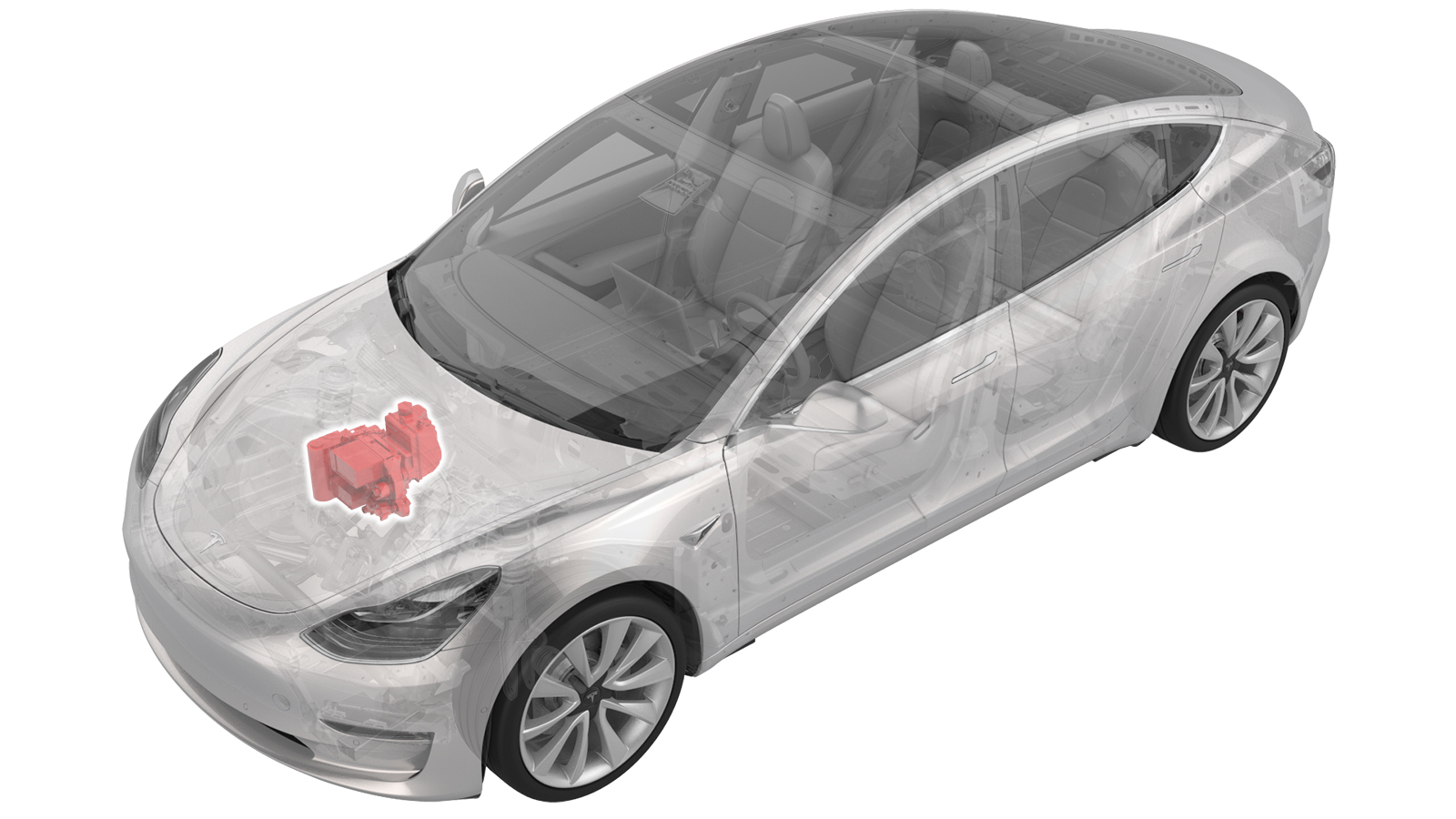
A/C Compressor, Supermanifold and Compressor to Supermanifold A/C Line (Heat Pump) (Remove and Replace)
 Correction code
18204012
1.92
NOTE: Unless otherwise explicitly
stated in the procedure, the above correction code and FRT reflect all of the work
required to perform this procedure, including the linked procedures. Do not stack correction codes unless
explicitly told to do so.
NOTE: See Flat Rate
Times to learn more about FRTs and how they are created.
NOTE: See Personal Protection to make sure wearing proper PPE when
performing the below procedure. NOTE: See Ergonomic Precautions for safe and healthy working
practices.
Correction code
18204012
1.92
NOTE: Unless otherwise explicitly
stated in the procedure, the above correction code and FRT reflect all of the work
required to perform this procedure, including the linked procedures. Do not stack correction codes unless
explicitly told to do so.
NOTE: See Flat Rate
Times to learn more about FRTs and how they are created.
NOTE: See Personal Protection to make sure wearing proper PPE when
performing the below procedure. NOTE: See Ergonomic Precautions for safe and healthy working
practices.
- 2026-07-03: Updated the steps to connect a LV maintainer.
- 2026-04-07: Updated the step to configure the compressor type.
- 2026-01-16: Updated flush time and amount of refrigerant required for flush procedure using Snap-On A/C machine.
- 2026-01-15: Correct socket size for nut that attaches the supermanifold to HVAC A/C line assembly to the supermanifold.
- 2025-12-10: Updated the procedure to reuse the supermanifold to HVAC A/C line after flushing.
- 2025-11-14: Add flush procedures by using Snap On machine.
- 2025-11-10: Added step to check installed part number revision to verify if retrofit procedure is necessary.
- 2025-10-27: Updated the A/C line HVAC side torque from 22Nm to 28Nm, and supermanifold side torque from 27Nm to 36Nm.
- 2025-08-14: Added steps of configuring the coolant pump type.
- 2025-03-27: Updated flush procedure.
- 2024-06-17: Added the step of updating coolant pump configuration.
- 2024-05-29: Updated the procedure per the latest validation.
- 2024-03-28: Fixed bad flush link.
- 2024-03-06: Updated the routines.
- 2024-02-05: Added steps to hand-tighten the bolts that attach the supermanifold and the compressor to the shock tower brace.
Equipment:
- 1600279-00-A A/C Oil Flush Adapter Set
- 1838504-C0-A, 1838504-E0-A, 1838504-N0-A Debris Flush Adapter
- 1711245-00-A - Snap On Ecotechnics Dual Gas A/C Machine, includes Flush Adapter Kit R134A & R1234YF or
- 1120026-01-A A/C SERVICE MACHINE, WAECO, ASC5500 RPA
Remove
- Set up the A/C machine.
- Raise and support the vehicle.
-
Open all four doors and lower the
windows.
NoteLatch rear doors to prevent accidental closing when 12V/LV power is disconnected.
- Remove the underhood storage unit. See Underhood Storage Unit (Remove and Replace).
- Place the vehicle in Service Mode. See Service Mode.
-
Check the thermal alerts via the
touchscreen by pressing the alert icon.
If one or more of the following alerts are present, perform a full flush later in the procedure.
- VCFRONT_a161_compressorSelfFault
- VCFRONT_a163_compressorDisabledFSR
- VCFRONT_a460_hardIsentropicTdFailed
- VCFRONT_a467_lowPowerIndexFlagged
- VCFRONT_a531_lowPowerIndexFlaggedUserFacing
- VCFRONT_a543_compressorLowFlowDeliveryDetected
- On the touchscreen, touch and select Run to start the "Start Thermal Fill Drain (Coolant & Refrigerant)" routine.
- Disconnect 12V/LV power. See 12V/LV Power (Disconnect and Connect).
- Remove the front aero shield panel. See Panel - Aero Shield - Front (Remove and Replace).
- Recover the refrigerant from the vehicle. See A/C Refrigerant (Recovery and Recharge).
- Remove the fresh intake duct. See Duct - Fresh Intake (Remove and Replace).
- Perform Vehicle HV Disablement Procedure. See Vehicle HV Disablement Procedure.
- Position the coolant underneath the front of the vehicle.
- Remove the coolant bottle cap.
-
Disconnect the powertrain bypass hose
from the Supermanifold.
NoteThis will drain the coolant reservoir.
-
Disconnect the radiator outlet hose
from the Supermanifold.
-
Disconnect the radiator inlet hose
from the Supermanifold.
-
Install three male plugs into the
coolant ports at the front of the Supermanifold.
-
Before performing the next two steps,
inspect the coolant hose temperature sensors and connectors.
NoteIf the vehicle is equipped with an earlier model temperature sensor (left image), the new super manifold connectors may not fit. In this case the electrical connector cover must be swapped from the old supermanifold to the new supermanifold. Perform GUID-3CE85A94-29EB-4E1D-8F60-F475FCF997A2.html#TASK_REWORK_CONNECTOR before installation.
-
Disconnect the sensor for the chiller
to battery hose.
-
Disconnect the sensor for the
powertrain supply hose.
-
Disconnect the chiller to battery hose
from the supermanifold.
-
Disconnect the powertrain supply hose
from the supermanifold.
-
Disconnect the HV battery return hose
from the Supermanifold.
-
Install three male plugs into the
coolant ports at the rear of the Supermanifold.
-
Disconnect the supermanifold harness
connector from the front controller.
-
Remove the clip that attaches the
thermal sub assembly harness to the front harness guide cover.
- Remove the 12V/LV battery. See 12V/LV Battery (Remove and Replace).
-
Release the clips (x2) that attach the coolant hose to the A/C
compressor bracket.
- Remove the clip that attaches the A/C compressor logic harness to the A/C compressor HV harness bracket.
-
Release the connector locking tab, and
then disconnect the low voltage electrical connector from the A/C compressor.
CAUTIONDO NOT push down on the red locking tab. Pull the tab away from the connector until the connector is unlocked, and then continue pulling the main body of the connector to fully disconnect it.
-
Remove the bolt that attaches the HV
harness bracket to the A/C compressor.
TIpUse of the following tool(s) is recommended:
- 13 mm socket
- Cordless Ratchet/Impact Driver
- Ratchet/torque wrench
-
Remove the bolt that attaches the
ground strap to the A/C compressor, and then set the ground strap aside.
TIpUse of the following tool(s) is recommended:
- Torx T25 socket
- Cordless Ratchet/Impact Driver
- Ratchet/torque wrench
-
Release the clip that attaches the
coolant hose to the A/C compressor bracket, near the ground strap attachment
point.
-
Pull the A/C compressor HV connector
black locking tab away from the A/C compressor.
-
Using a 45-degree pick, simultaneously
push on the central locking tab while pulling on the outer locking tab, and remove the
HV connector from the A/C compressor.
-
Disconnect the HVIL electrical
connector.
- After A/C recovery is completed, remove the A/C hoses from the vehicle.
-
Remove the nut that attaches the
supermanifold to compressor suction line to the compressor.
NoteUse of the following tool(s) is recommended:
- 13 mm deep socket
- Flex head ratchet/flex head torque wrench
-
Remove the nut that attaches the
supermanifold to compressor discharge line to the compressor.
NoteUse of the following tool(s) is recommended:
- 13 mm deep socket
- Flex head ratchet/flex head torque wrench
-
Remove the bolt on the A/C manifold to
compressor line from the Supermanifold, and then remove the A/C manifold line from the
vehicle.
TIpUse of the following tool(s) is recommended:
- 13 mm socket
- 6 in extension
- Flex head ratchet/flex head torque wrench
-
Remove the bolts (x2) that attach the
supermanifold to HVAC A/C line to the HVAC assembly.
TIpUse of the following tool(s) is recommended:
- 13 mm socket
-
Remove the rear battery tie down strap
from the 12V/LV battery bracket.
NoteThe 12V/LV battery bracket also functions as the A/C compressor bracket.
-
Release the clip that attaches the
12V/LV battery vent tube to the battery bracket.
-
Release the clip that attaches the A/C
compressor low voltage harness to the A/C compressor HV harness bracket.
-
Move the HV harness bracket forward
and up to release the bracket from the A/C compressor, and then carefully set the
bracket aside.
-
Remove the retaining clips that attach
the A/C compressor HV harness to the shock tower support brace.
NotePull upward on clip to assist with removal, Do not pull on HV cable.
-
Remove the LH and RH bolts that attach
the shock tower brace to the body.
 55 Nm (40.6 lbs-ft)
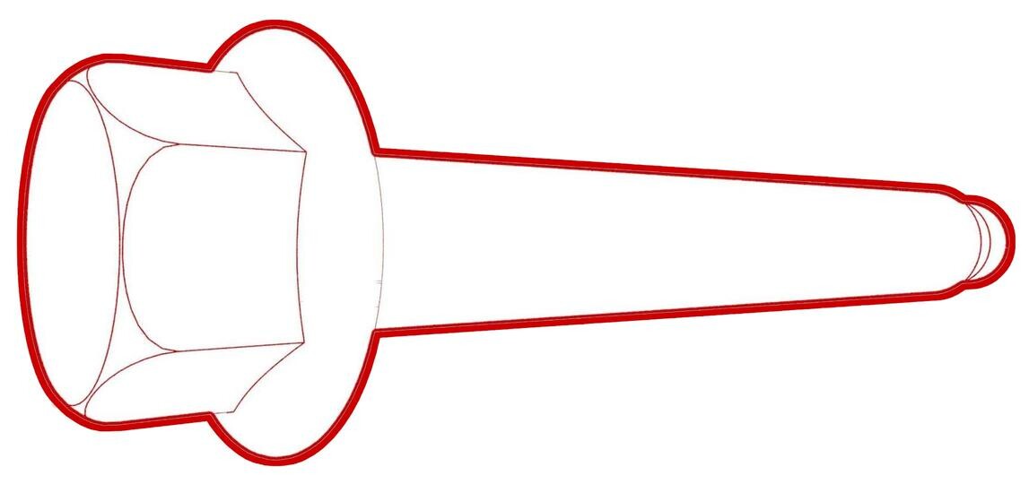 55 Nm (40.6 lbs-ft)TIpUse of the following tool(s) is recommended:
- 15 mm socket
- Flex head ratchet/flex head torque wrench
-
Remove the LH and RH outer bolts that
attach the shock tower brace to the body, and then remove the shock tower brace from the
vehicle.
 62 Nm (45.7 lbs-ft)TIpUse of the following tool(s) is recommended:
- 15 mm socket
- Flex head ratchet/flex head torque wrench
-
With assistance, remove the shock
tower brace along with Supermanifold and compressor from the vehicle.
NoteMind the connectors and A/C lines, then slowly lift the brace. Put it on a cardboard pad.
-
Remove the nut that attaches the
supermanifold to HVAC A/C line assembly to the supermanifold, and remove the
supermanifold to HVAC A/C line assembly.
TIpUse of the following tool(s) is recommended:
- 13 mm socket
- Cordless Ratchet/Impact Driver
- Flex head ratchet/flex head torque wrench
-
Document the old and new part numbers
and serial numbers.
NoteLabel is located in front of accumulator.
-
Remove the bolts (x2) that attach the
supermanifold to the shock tower brace, and then remove the supermanifold.
TIpUse of the following tool(s) is recommended:
- 15 mm socket
- Cordless Ratchet/Impact Driver
- Flex head ratchet/flex head torque wrench
-
Remove the bolts (x2) that attach the
A/C compressor bracket to the shock tower brace, and then remove the A/C compressor and
A/C compressor bracket assembly.
NoteUse of the following tool(s) is recommended:
- 15 mm socket
- Flex head ratchet/flex head torque wrench
-
Remove A/C compressor bracket from the
A/C compressor.
NoteUse of the following tool(s) is recommended:
- 10 mm deep socket
- Flex head ratchet/flex head torque wrench
- Document the part numbers of the new and old compressors to update the configuration in a later step.
Flush HVAC system and prepare components for Snap-On A/C Machine
-
Temporarily install the old Supermanifold to HVAC A/C line, and install the bolts
(x2) (Torque 28 Nm) that attach the line to the HVAC assembly
-
Install the flush adapter 1838504-E0-A
to the Supermanifold to HVAC A/C line.
Note1x nut, 13mm, 36 Nm
-
Connect the HVAC case flush adapter to
the A/C machine.
NoteConnect the red pressure line to the left side of the adapter, bolt the blue line coming from the flush kit to the right side of the adapter.
-
Connect Snap on A/C machine hoses to
the A/C flush adapters and run the flush procedure by selecting .
NoteThe flush procedure runs for approximately 90 minutes, a minimum of 3.2 kg of refrigerant is needed in the tank to run the system flush procedure.
-
Disconnect the flush adapter from the
A/C machine.
- Remove the coolant drain container from underneath the vehicle.
-
Remove the A/C line plugs from the new
Supermanifold.
-
Install the plug into the old
Supermanifold to HVAC lines holes.
NoteTry to avoid oil leakage as much as possible.
-
Install the plug into the old
Supermanifold to A/C compressor lines hole.
NoteTry to avoid oil leakage as much as possible.
-
Prepare the part for MRB shipment as a
special interest.
NoteUnplug all the Coolant Only plugs from the Supermanifold and drain as much coolant as you can to the Low Profile Fluid Receiver. Carefully pack it to the box in the same way how the new one was there. Write down the Toolbox Session number, Tesla Model, and the last 6 digits of the VIN.
- Remove the existing supermanifold to HVAC A/C line from the HVAC.
-
Install new seal washers to the
existing supermanifold to HVAC A/C line at the supermanifold side.
Note1111740-00-A WASHER,3/4,STEEL ZN,SEAL (x1), 1111738-00-A WASHER,1/2,STEEL ZN,SEAL (x1), 1111737-00-A WASHER, 3/8, STL ZN, SEAL (x3).
-
Install the supermanifold to HVAC A/C
line assembly to the supermanifold and install the nut hand tight.
Note1x nut, 13mm, 36 Nm. Torque at a later step.
-
Remove the A/C compressor bracket from
the A/C compressor
Note3x bolts, 10mm, 9 Nm
-
Remove transportation plugs from the
new A/C compressor
-
Prepare the part for MRB shipment as a special interest
NoteInstall transportation plugs from the new A/C compressor to the old compressor to avoid oil leakage during the transportation
-
Install the A/C compressor bracket to
the A/C compressor
Note3x bolts, 10mm, 9 Nm
-
Overlap from A/C system flush procedure
NoteSubtract time spent on other operations while waiting for A/C system flush, fast flush is 40 minutes, full flush is 1 hour and 40 minutes
-
Disconnect the low pressure hose from the A/C machine to the quick connector of the
filter
-
Disconnect HVAC case flush adapter
from A/C machine
NoteDisconnect the red pressure line to the left side of the adapter, unscrew the blue line coming from the flush kit to the right side of the adapter
-
Remove adapter from vehicle
Note1x nut, 13mm, 36 Nm
-
Remove the bolts (x2) that attach the supermanifold to HVAC A/C line to the HVAC
assembly, and then remove the A/C line from the vehicle.
Flush HVAC system and prepare components for Waeco A/C Machine
-
Temporarily install the old
Supermanifold to HVAC A/C line, and install the bolts (x2) (Torque 28 Nm) that attach
the line to the HVAC assembly
-
Install the flush adapter to the
Supermanifold to HVAC A/C line.
Note1x nut, 13mm, 36 Nm
-
Set up flush kit to A/C machine.
NoteAttach the flush kit to the Waeco A/C machine. 2x bolts, 8mm, 1x Nyloc nut
-
Inspect the liquid line filter drier
marking.
NoteMark the filter before every flush with paint marker, replace the filter after 10 flushes.NoteIf replacement of the filter is not yet necessary, go to step 7.
-
Remove the liquid inline filter
drier
NoteRemove the filter from the container (the grey filter attached to the flush unit) PR052FM, Good to re-use copper o-ring, use hand force no tools
-
Replace the liquid inline filter drier
(the grey filter attached to the flush unit) PR052FM
Note1x new filter, 2x new copper sealing rings, Wear appropriate PPE, Swap the nipple from old to new filter, Install copper sealing ring between connections, Do not over tighten, hand tight, due to copper line Ensure old sealing was removed before installing new filter, use pick tool to remove copper ring if needed
-
Connect the low pressure hose from the
A/C machine to the quick connector of the filter
-
Connect the HVAC case flush adapter to
A/C machine
NoteConnect the red pressure line to the left side of the adapter, bolt the blue line coming from the flush kit to the right side of the adapter
-
Connect A/C machine hoses to A/C flush
adapters and flush the HVAC case.
NoteIf one or more of the alerts mentioned in step 6 of the 'Remove' section are present, choose Full flushing. If no alerts are present, choose Fast flushing.NoteFast flush procedure runs for approximately 40 minutes. If one of the Illustrated alerts are present, run full flush. This takes around 1 hours and 40 minutes. Must use A/C Service Machine WAECO ASC 5500G RPA R1234YF. A minimum of 6 kg of refrigerant is needed in the tank to run the system flush procedure. Press Enter => Other Selections => Enter => Flushing => Enter => Enter => Enter =>=> Full Flushing => Enter
- Remove the coolant drain container from underneath the vehicle.
-
Remove the A/C line plugs from the new
Supermanifold
-
Install plug into the old
Supermanifold to HVAC lines holes
NoteTry to avoid oil leakage as much as possible
-
Install plug into the old
Supermanifold to A/C compressor lines holes
NoteTry to avoid oil leakage as much as possible
-
Prepare the part for MRB shipment as a
special interest
NoteUnplug all the Coolant Only plugs from the Supermanifold and drain as much coolant as you can to the Low Profile Fluid Receiver,Carefully pack it to the box in the same way how the new one was there, Write down the Toolbox Session number,Tesla Model, last 6 digits of VIN
-
Install supermanifold to HVAC A/C line
assembly to supermanifold and install nut hand tight
Note1x nut, 13mm, 36 Nm, Torque at later step
-
Remove the A/C compressor bracket from
the A/C compressor
Note3x bolts, 10mm, 9 Nm
-
Remove transportation plugs from the
new A/C compressor
-
Prepare the part for MRB shipment as a
special interest
NoteInstall transportation plugs from the new A/C compressor to the old compressor to avoid oil leakage during the transportation
-
Install the A/C compressor bracket to
the A/C compressor
Note3x bolts, 10mm, 9 Nm
-
Overlap from A/C system flush
procedure
NoteSubtract time spent on other operations while waiting for A/C system flush, fast flush is 40 minutes, full flush is 1 hour and 40 minutes
-
Disconnect the low pressure hose from
the A/C machine to the quick connector of the filter
-
Disconnect HVAC case flush adapter
from A/C machine
NoteDisconnect the red pressure line to the left side of the adapter, unscrew the blue line coming from the flush kit to the right side of the adapter
-
Remove adapter from vehicle
Note1x nut, 13mm, 36 Nm
Install
-
Install the NVH acoustic cover onto
the new compressor.
NoteInstall a new cover or reuse the old cover if the adhesive is in usable condition and a new cover is not available.NoteRemove the adhesive backing, and then lay the cover down with the adhesive side facing up. Align the cutouts to the suction port on the compressor, install the cover around the suction port, and then continue to wrap the cover around the compressor.
-
Position the A/C compressor bracket on
the A/C compressor, and then install the bolts that attach the bracket to the
compressor.
 9 Nm (6.6 lbs-ft)NoteUse of the following tool(s) is recommended:
- 10 mm deep socket
- Flex head ratchet/flex head torque wrench
-
Position the A/C compressor and A/C
compressor bracket assembly to the strut shock tower brace, and then hand-tighten the
bolts (x2) to secure.
-
Remove the bolts (x2) that attach the
supermanifold to HVAC A/C line to the HVAC assembly, and then remove the A/C line from
the vehicle.
-
Replace the seal washers of the existing supermanifold to HVAC A/C line at the
supermanifold side.
Note1111740-00-A WASHER,3/4,STEEL ZN,SEAL (x1), 1111738-00-A WASHER,1/2,STEEL ZN,SEAL (x1), 1111737-00-A WASHER, 3/8, STL ZN, SEAL (x3).NoteLubricate seal washers with ND-11 oil.
- Remove the A/C line plugs from the new supermanifold.
-
Replace the seal washers on
supermanifold to HVAC A/C line assembly on the HVAC side.
Note1111740-00-A WASHER,3/4,STEEL ZN,SEAL (x1), 1111738-00-A WASHER,1/2,STEEL ZN,SEAL (x1), 1111737-00-A WASHER, 3/8, STL ZN, SEAL (x3).NoteLubricate seal washers with ND-11 oil.
-
Hand-tighten the nut that attach the
supermanifold to HVAC A/C line assembly to the supermanifold.
-
Torque the nut that attach the
supermanifold to HVAC A/C line assembly to the supermanifold.36 Nm (26.5 lbs-ft)NoteUse of the following tool(s) is recommended:
- 13 mm socket
- Flex head ratchet/flex head torque wrench
- 6 in extension
-
Position the supermanifold assembly to
the shock tower brace, and then hand-tighten the bolts that attach the supermanifold
assembly to the brace.
-
Tighten the bolts that attach the
supermanifold assembly to the shock tower brace.31 Nm (22.9 lbs-ft)NoteUse of the following tool(s) is recommended:
- 15 mm socket
- Flex head ratchet/flex head torque wrench
- 6 in extension
-
Tighten the bolts (x2) that attach the
compressor to the strut shock tower brace.31 Nm (22.9 lbs-ft)NoteUse of the following tool(s) is recommended:
- 15 mm deep socket
- Flex head ratchet/flex head torque wrench
-
With assistance, install the
supermanifold and compressor along with shock tower brace to the vehicle.
Note2 technicians are required for this step, Mind the connectors and A/C lines, slowly lift the brace.
-
Install the LH and RH bolts that
attach the shock tower brace to the body.55 Nm (40.6 lbs-ft)55 Nm (40.6 lbs-ft)NoteUse of the following tool(s) is recommended:
- 15 mm socket
- Flex head ratchet/flex head torque wrench
-
Install the LH and RH outer bolts that
attach the shock tower brace to the body.62 Nm (45.7 lbs-ft)NoteUse of the following tool(s) is recommended:
- 15 mm socket
- Flex head ratchet/flex head torque wrench
-
Install the bolts (x2) that attach the
supermanifold to HVAC A/C line to the HVAC assembly.28 Nm (20.6 lbs-ft)TIpUse of the following tool(s) is recommended:
- 13 mm socket
-
Install the radiator inlet hose to the
Supermanifold.
NotePerform a push-pull-push test to make sure the hose is fully seated. Do not wiggle the hose at the connection.
-
Install the radiator outlet hose to
the Supermanifold.
NotePerform a push-pull-push test to make sure the hose is fully seated. Do not wiggle the hose at the connection.
-
Install the powertrain bypass hose to
the Supermanifold.
NotePerform a push-pull-push test to make sure the hose is fully seated. Do not wiggle the hose at the connection.
-
Connect the HV battery return hose to
the Supermanifold.
NotePerform a push-pull-push test to make sure the hose is fully seated. Do not wiggle the hose at the connection.
-
Connect the powertrain supply hose to
the Supermanifold.
NotePerform a push-pull-push test to make sure the hose is fully seated. Do not wiggle the hose at the connection.
-
Connect the chiller to battery hose to
the Supermanifold.
NotePerform a push-pull-push test to make sure the hose is fully seated. Do not wiggle the hose at the connection.
-
Connect the sensor for the powertrain
supply hose.
NoteHarness and coolant hose are color coded. Match harness color to coolant hose color.
-
Connect the sensor for the chiller to
battery hose.
NoteHarness and coolant hose are color coded. Match harness color to coolant hose color.
-
Install the clip that secures the
thermal sub assembly harness to the front harness guide cover.
-
Connect the thermal sub-harness
connector to the front controller.
-
Position the A/C compressor HV harness
bracket on the A/C compressor.
NoteMake sure the HV harness bracket engages with the harness mount on the top of the A/C compressor.
-
Install the bolt that attaches the HV
harness bracket to the A/C compressor.9 Nm (6.6 lbs-ft)TIpUse of the following tool(s) is recommended:
- 13 mm deep socket
- Ratchet/torque wrench
TIp -
Connect the HVIL electrical
connector.
-
Fully seat the A/C compressor HV
connector on the A/C compressor, and then engage the locking tab by pushing it toward
the A/C compressor.
NotePerform a push-pull test to verify that the connector is fully attached.
-
Install the retaining clips that
secure the A/C compressor HV harness to the shock tower brace.
-
Install the clip that attaches the
coolant hose to the A/C compressor bracket, near the ground strap attachment
point.
-
Position the ground strap on the A/C
compressor, and then install the bolt that attaches the ground strap to the A/C
compressor.7 Nm (5.2 lbs-ft)NoteThis bolt is self-tapping. It is not necessary to tap the compressor bolt hole.TIpUse of the following tool(s) is recommended:
- Torx T25 socket
- Cordless Ratchet/Impact Driver
- Ratchet/torque wrench
-
Install the clip that attaches the A/C
compressor low voltage harness to the A/C compressor HV harness bracket.
-
Connect the low voltage electrical
connector to the A/C compressor, and then engage the locking tab.
CAUTIONPush the red locking tab towards the connector to engage the locking mechanism. DO NOT push down or pull up on the red locking tab.
-
Remove transportation plugs from the
new A/C compressor.
-
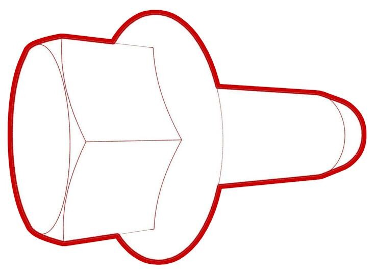
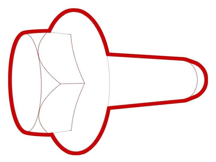
Lubricate the O-rings on the high
pressure and low pressure supermanifold to A/C compressor hose fittings of the new A/C
line with the appropriate A/C oil. See Fluids and Capacities for A/C oil specifications.
Figure 1. Low pressure fitting shown; high pressure fitting similar -
Position the supermanifold to A/C
compressor high pressure fitting on the A/C compressor, and then install the nut that
attaches the fitting to the A/C compressor.22 Nm (16.2 lbs-ft)TIpUse of the following tool(s) is recommended:
- 13 mm deep socket
- Flex head ratchet/flex head torque wrench
-
Position the supermanifold to A/C
compressor low pressure fitting on the A/C compressor, and then install the nut that
attaches the fitting to the A/C compressor.22 Nm (16.2 lbs-ft)TIpUse of the following tool(s) is recommended:
- 13 mm deep socket
- Position the supermanifold to compressor A/C line onto the supermanifold, and then hand tighten the bolt that attaches the A/C line to the supermanifold.
-
Torque the bolt that attaches the supermanifold to compressor A/C line to the
supermanifold.22 Nm (16.2 lbs-ft)NoteUse of the following tool(s) is recommended:
- 13 mm socket
- Flex head ratchet/flex head torque wrench
- 6 in extension
-
Install the clips (x2) that attach the coolant hose to the A/C
compressor bracket.
-
Install the rear battery tie down
strap on the 12V battery bracket.
-
Install the clip that attaches the 12V
battery vent tube to the 12V battery bracket.
- Install the 12V/LV auxiliary battery. See 12V/LV Battery (Remove and Replace).
- Connect first responder loop and LV battery.
- On the touchscreen, touch and select Run to start the "Start Thermal Fill Drain (Coolant & Refrigerant)" routine.
- Disconnect 12V/LV power. See 12V/LV Power (Disconnect and Connect).
- Perform A/C vacuum leak test. See A/C Refrigerant (Recovery and Recharge).
- Perform A/C refrigerant recharge. See A/C Refrigerant (Recovery and Recharge).
- Perform a cooling system vacuum refill. See Cooling System (Vacuum Refill).
- Connect 12V/LV power. See 12V/LV Power (Disconnect and Connect).
- Connect a LV maintainer. See LV Maintainer (Connect and Disconnect).
- Enable Service Mode Plus. See Service Mode Plus.
-
Set the compressor Type using the touchscreen:
- For vehicles that run firmware version 2026.2.3 or later (NA/EMEA) or 2025.44.32 or later (APAC), touch , and then touch Run to start the routine.
- For vehicles that run earlier firmware versions, touch , and then select and save the correct compressor type
NoteIn case the routine did not complete successfully, refer to Toolbox article 5696900 for compressor configuration.NoteCheck the Gateway configuration for compressorType and make sure it shows as intended. -
For vehicles built in Giga Berlin
only: On the touchscreen, tap and update refrigACLineType configuration to one of the following values:
- If part number 1502020-00-B or newer is installed: CONTI_LIMITED
- If part number 1625910-00-C or -D is installed: SAAA_LIMITED
- If part number 1625910-00-E or newer is installed: UNLIMITED
- If part number 1807596-XX-X is installed: UNLIMITED
- Reinstall the firmware. See Software Reinstall - Touchscreen.
- On the touchscreen, tap the Service Mode "wrench" (at the bottom of the touchscreen UI), and then tap , and allow the routine to complete.
- Tap to inspect the current coolant pump configuration. If the configuration is not DUAL_MIX, change it to DUAL_MIX.
- Tap , and close once the routine is passed.
- Tap to inspect the current supermanifold configuration. If the configuration is not TYPE1, change it to TYPE1.
- Tap , and close once the routine is passed.
- Tap , and close once the routine is passed.
- Tap , and close once the routine is passed.
- Install the 2nd row lower seat cushion. See Seat Cushion - Lower - 2nd Row (Remove and Replace).
- Install the front aero shield panel. See Panel - Aero Shield - Front (Remove and Replace).
- After the coolant air purge is finished. inspect the coolant level and make sure the fluid level is at the Max line.
- Tap , and close once the routine is passed.
- Tap , and close once the routine is passed.
- On the touchscreen, press and hold the Exit Service Mode button to exit Service Mode Plus.
- Disconnect the LV maintainer. See LV Maintainer (Connect and Disconnect).
- Install the fresh intake duct. See Duct - Fresh Intake (Remove and Replace).
- Install the underhood storage unit. See Underhood Storage Unit (Remove and Replace).