HV Battery (AWD) (Remove and Install)
Correction codes 16010201 3.60 NOTE: Unless otherwise explicitly stated in the procedure, the above correction code and FRT reflect all of the work required to perform this procedure, including the linked procedures. Do not stack correction codes unless explicitly told to do so. NOTE: See Flat Rate Times to learn more about FRTs and how they are created. NOTE: See Personal Protection to make sure wearing proper PPE when performing the below procedure. NOTE: See Ergonomic Precautions for safe and healthy working practices.
- 2025-10-13: Updated procedure so that the coolant vacuum fill is performed before LV is reconnected.
- 2025-10-10: Changed procedure sequence for cleaning the HV busbar and HV header connector contact surfaces.
- 2025-10-10: Updated steps to remove/install the bolts (x4) that attach the front of the HV battery to the vehicle. Added note and updated image to show vehicle without skid plate.
- 2025-01-08: Added images of HV battery alignment rods for clarification.
- 2024-06-13: Updated lift pad adapter PNs.
- 2023-11-21: Added new lift pad instructions.
- 2023-08-23: Updated EPB Service Mode reference.
- 2023-08-14: Added notes about vacuum refill requirement when the coolant loss is greater than 1L.
- 2023-07-11: Reorganized steps to accommodate service while standing.
- 2023-05-22: Added caution for correct positive DC cable connection.
Equipment:
- 1936724-00-A - Universal Lift Pad Adapters
- 1133787-00-A Key, Seat Belt Release, Model 3
- 1020566-00-F ASY, Battery Table, Manual Lift
- 1020566-99-A Top Plate, Battery Table, Manual Lift
- 1129166-00-A Hoist, H-Frame EMEA
- 1134523-00-A Kit, Alignment Rods, Battery, Model 3
- 1140311-00-A Lever Lock, HV Connector, Model 3
- 1053600-00-B Drive Unit Pressure Test Fixture
- 1130942-00-B Adapter, Coolant Reservoir Pressure Test
- 1132185-00-B Kit, Coolant Leak Test Adapters, Model 3
- 1133843-00-A Kit, Coolant Drain & Fill Adapters, M3
- 1135762-00-A Kit, Svc Plug, Cooling Hose, Model 3
- 1065131-00-A Kit, Battery Coolant Drain and Fill
- 1026636-00-A Pack Enclosure Leak Tester, HV Battery
- 1140501-00-A Pack Kit, Enclosure, Leak Test, HV Battery, Complete
- 1144879-00-A Kit, Encl Leak Test Adapters, HV Battery
- 1108272-00-B Cap, Logic Conn, Inv, 3DU
Only
technicians who have completed all required certification courses are permitted to
perform this procedure. Tesla recommends third party service provider technicians
undergo equivalent training before performing this procedure. For more information on
Tesla Technician requirements, or descriptions of the subject matter for third parties,
see HV Certification Requirements. Proper personal protective equipment (PPE) and insulating HV
gloves with a minimum rating of class 0 (1000V) must
be worn at all times a high voltage cable, busbar, or fitting is handled. Refer to Tech Note TN-15-92-003, High Voltage Awareness
Care Points
for additional safety
information.
Remove
- Remove the LH and RH lower rocker panel covers. See Cover - Rocker Panel - Lower - LH (Remove and Replace).
-
Open all doors.
NoteLatch the rear doors to prevent accidental lockout.
- Lower all windows.
- Remove the rear underhood apron. See Underhood Apron - Rear (Remove and Replace).
- Remove the cabin intake duct. See Duct - Upper - Cabin Intake (Remove and Replace).
- Move the driver seat fully rearwards.
- Remove the LH instrument panel end cap. See End Cap - Instrument Panel - LH (Remove and Replace).
- Remove the LH middle A-pillar trim. See Trim - A-Pillar - Middle - LH (Remove and Replace).
- Remove the LH lower A-pillar trim. See Trim - A-Pillar - Lower - LH (Remove and Replace).
- Remove the driver footwell cover. See Cover - Footwell - Driver (Remove and Replace).
- Remove the LH front floor mat.
- Remove the LH center console side panel carpet. See Side Panel - Center Console - LH (Remove and Replace).
- Move the front passenger seat fully rearwards.
- Remove the RH instrument panel end cap. See End Cap - Instrument Panel - LH (Remove and Replace).
- Remove the RH middle A-pillar trim. See Trim - A-Pillar - Middle - LH (Remove and Replace).
- Remove the RH lower A-pillar trim. See Trim - A-Pillar - Lower - LH (Remove and Replace).
- Remove the front passenger footwell cover. See Cover - Footwell - Passenger (LHD) (Remove and Replace).
- Remove the RH front floor mat.
- Remove the RH center console side panel carpet. See Side Panel - Center Console - LH (Remove and Replace).
- Move the driver and front passenger seats fully forward.
- Remove the 2nd row floor mat from the vehicle.
- Remove the 2nd row lower seat cushion. See Seat Cushion - Lower - 2nd Row (Remove and Replace).
- Remove the RH 2nd row seat side bolster. See Bolster - Side - Seat - 2nd Row - LH (Remove and Replace).
- Remove the RH rear sill panel trim. See Trim - Sill Panel - Rear - LH (Remove and Replace).
- Remove the RH upper B-pillar trim. See Trim - B-Pillar - Upper - LH (Remove and Replace).
- Remove the RH lower B-pillar trim. See Trim - B-Pillar - Lower - LH (Remove and Replace).
- Repeat step 23 through step 26 for the LH side of the vehicle.
-
Remove the clips (x4) and hook-and-loop strips that attach the rear carpet to the vehicle.
NoteThe number of clips on newer vehicles might vary.
-
Lift up the RH side of the rear carpet and insert a hand to feel if the 4th RH HV battery bolt is present. If the bolt is present, then remove the bolt.
-
Lift up the LH side of the rear carpet and insert a hand to feel if the 4th LH HV battery bolt is present. If the bolt is present, then remove the bolt.
- Move the driver seat fully rearwards.
-
Remove the clips (x3) that attach the LH front carpet to the vehicle.
-
Fold the LH front carpet for access, and then release the seat harness from the clip to allow the carpet to fold back further.
NoteThe driver footrest is part of the LH front carpet.
-
Remove the LH front inner HV battery bolts.
-
Check to see if the 3rd LH HV battery bolt is present. If the bolt is present, remove the bolt.
-
Remove the 3rd LH inner HV battery bolt.
- If the vehicle had the 3rd or the 4th LH inner HV battery bolts, move the driver seat to the center position and the seat back to the upright position. Otherwise, skip to the next step.
-
Separate the LH side of the rear main carpet perforations to access the 4th LH inner HV battery bolt, if the bolt is present.
NoteMight need to undo the hook-and-loop strips that are attach the front carpets to the body.NoteMight need to move the driver seat forwards or rearwards if necessary to allow access for the bolt.
-
Remove the 4th LH inner bolt that attaches the HV battery to the body.
-
Remove the 5th LH rear inner bolt that attaches the HV battery to the body.
NoteLift up the rear main carpet for access.
-
Unfold the LH front carpet back to its original position.
NoteMove the front edge down, and then slide back the carpet to ease positioning.
- Move the front passenger seat fully rearwards.
-
Remove the clips (x4) that attach the RH front carpet to the vehicle.
-
Release the seat electrical harness from the clips to allow the RH front carpet to fold back more.
-
Remove the RH front inner bolts (x2) that attach the HV battery to the body.
-
Check if the 3rd RH bolt is present. Use a flashlight, if needed. Remove the bolt, if present. Otherwise, skip to the next step.
-
Move the front passenger seat to the center position and the seatback to the upright position, if the 3rd RH and 4th RH inner HV battery bolts are present.
NoteMight need to undo the hook-and-loop strips that are attach the front carpets to the body.NoteMight need to move the driver seat forwards or rearwards if necessary to allow access for the bolt.
-
Remove the 4th RH inner bolt that attaches the HV battery to the body, if equipped. Otherwise, skip to the next step.
-
Remove the 5th RH rear inner bolt that attaches the HV battery to the body.
- Put chocks on one of the rear wheels to prevent the vehicle from rolling.
- Enable the EPB Service Mode. See Parking Brake - Caliper - Rear - LH (Release)
- Connect a laptop with Toolbox 3 to the vehicle. See Toolbox (Connect and Disconnect).
-
Click Actions, type "thermal" in the search field, click the play button next to PROC_VCFRONT_X_THERMAL-FILL-DRAINvia Toolbox:(link), and then select Run.
NoteThe 5-way valve is set to Series position, and the coolant pumps are disabled.
- Remove the laptop from the vehicle, but do not close Toolbox.
- Disconnect 12V power. See 12V/LV Power (Disconnect and Connect).
- Perform Vehicle HV Disablement Procedure. See Vehicle HV Disablement Procedure.
-
Remove the HV cap that covers the HV harness located on the LH side of the ancillary bay.
-
Remove the bolts that attach the charge port to HV battery harness bracket at the ancillary bay.
- If the HV battery DC input is configured with busbars, continue to the next step, otherwise skip to step 63.
-
Remove the bolt that secures the charge port busbar connector access door.
-
Remove the bolts (x2) that attach the charge port busbar connector to the DC input HV header, and then lift to remove the connector from the header.
- Skip to step 66.
-
Slide the release to unlock the DC input connector handle of the charge port to HV battery harness from the secured position.
-
Fully raise the handle on the DC input connector.
- Remove the DC input connector from the ancillary bay DC input header.
- If the charge port to HV battery harness has a 3-phase connector, continue to the next step, otherwise skip to step 70.
-
Slide the release to unlock the 3-phase connector handle of the charge port to HV battery harness from the secured position.
-
Fully raise the handle on the 3-phase connector.
- Remove the 3-phase connector from the ancillary bay 3-phase header.
-
Release the clip that attaches the charge port to HV harness connector at the sill area.
-
Remove the bolts that attach the LH and RH inner ancillary bay rails to the ancillary bay cover.
- Remove the DCDC ground busbar. See Busbar - DCDC Ground (Remove and Replace).
-
Remove and discard the nut that attaches the positive 12V output cable to the DCDC passthrough, and then remove the cable from the passthrough.
NoteInspect the condition of the rubber boot at the end of the output cable, and replace the boot if it is melted or damaged.
- Partially close all doors in preparation for pushing the vehicle.
- Remove the wheel chocks from the wheel.
-
Remove the wheel chocks from the wheel, and with an assistant, push the vehicle to a lift, then re-chock the wheel.
CAUTIONPush the vehicle for a very short distance and at less than 1 MPH.
-
Install lift pad adapters.
- For EMEA only, install Adapter, Lift Pad, Model 3 (1453419-00-A)
- For other regions, install Universal Lift Pad Adapters (1936724-00-A)
WarningDO NOT use any other lift pad adapters.NoteOutside of EMEA, Universal Lift Pad Adapters (1936724-00-A) replace Adapter, Lift Pad, Model 3 (1453419-00-A). Discard any other versions of lift pad adapters.NoteIn EMEA, the Universal Lift Pad Adapters are not yet available. Make sure to use the rubber Model Y lift pads on Model Y and the Model 3 lift pads on Model 3.Instructions for Universal Lift Pad Adapters:
-
Raise the vehicle to a comfortable working height.
CAUTIONVerify that the vehicle is stable on the lift.
- Remove the front aero shield panel. See Panel - Aero Shield - Front (Remove and Replace).
-
Release the clips along the bottom edge of the LH and RH wheel arch liners.
- Install bungee straps to pull the LH and RH wheel arch liners away from the HV battery and expose the coolant hoses.
- Remove the front HV battery skid plate. See Skid Plate - HV Battery - Front (Remove and Replace).
-
Disconnect the electrical harness from the PTC heater HV connector, and then release the electrical harness from the bracket.
NoteThe PTC heater HV connector is only for vehicles without a heat pump. For vehicle with a heat pump, skip to the next step.
-
Disconnect the electrical harness from the A/C HV connector, and then release the electrical harness from the bracket.
-
Remove the bolt that attaches the front drive unit HV harness to the front drive unit.
-
Slide the release to unlock the front drive unit HV connector handle of the front drive unit to HV battery harness from the secured position.
-
Fully raise the handle on the front drive unit HV connector.
- Remove the front drive unit HV connector from the front drive unit HV header.
-
Remove the bolt that attaches the ground strap to the front drive unit.
-
Release the clip that attaches the front drive unit ground strap to the front drive unit.
-
Remove the bolt that attaches the ground strap bolt to the HV battery, and then remove the ground strap from the vehicle.
- Position a coolant drain under the front RH corner of the HV battery.
-
Release the clip and disconnect the powertrain return hose at the RH side of the vehicle, and immediately plug the male and female fittings.
-
Release the clip and disconnect the rear powertrain supply hose at the RH side of the vehicle, and immediately plug the male and female fittings.
- Position the coolant drain under the front LH corner of the HV battery.
-
Release the clip and disconnect the HV battery return hose at the LH side of the vehicle, and immediately plug the male and female fittings.
-
Release the clips that attach the battery to chiller hose to the body.
-
Release the clip and disconnect the chiller to HV battery hose from the manifold at the LH side of the vehicle, and immediately plug the male and female fittings.
- Remove the coolant drain from underneath the vehicle.
- Remove the mid aero shield panel. See Panel - Aero Shield - Rear (Remove and Replace).
- Put the support stand to support the front portion of the rear subframe.
-
Release the fir tree clips that attach the coolant hoses to the LH shear plate.
-
Remove the smaller bolts that attach the LH shear plate to the body.
-
Remove the larger bolt that attaches the LH shear plate and rear subframe to the body, and then remove the LH shear plate.
-
Re-install the larger bolt, and hand-tighten the bolt to the rear subframe.
- Repeat steps 102 through 105 for the RH shear plate.
- Remove the support stand from underneath the rear subframe
- Remove the rear HV battery skid plate. See Skid Plate - HV Battery - Rear (Remove and Replace).
- Position the coolant drain under the rear LH side of the HV battery.
-
Release the clip and disconnect the rear drive unit inverter inlet hose from the LH underside of the ancillary bay, and immediately plug the male and female fittings.
- Position the coolant drain under the rear RH side of the HV battery.
-
Release the clip and disconnect the coolant outlet hose from the powertrain return hose, and immediately plug the male and female fittings.
- Remove the coolant drain from underneath the vehicle.
-
Remove the nuts that attach the rear drive unit HV electrical harness bracket to the HV battery.
-
Slide the release to unlock the HV battery rear drive unit connector handle of the rear drive unit to HV battery harness from the secured position.
-
Fully raise the handle on the HV battery rear drive unit connector.
- Remove the HV battery rear drive unit connector from the HV battery header.
-
With an assistant, put the battery table in position, and then lower the vehicle to support the HV battery.
NoteLine up the battery table so that the center 4 bolts of the HV battery are accessible through the opening in the battery table.
-
Remove the center bolts (x4) that attach the HV battery through the HV battery center rail ski cover.
-
Remove the bolts (x8) that attach the HV battery LH and RH support brackets to the vehicle.
-
Remove the front center bolt that attaches the HV battery to the vehicle.
-
Where fitted: remove the bolts (x4)
that attach the front of the HV battery to the vehicle.
-
Remove the bolts (x16) that attach the HV battery to the vehicle.
NoteRecord the positions of any installed washers, as they will be reinstalled to the same locations during the installation procedure.
- With an assistant, raise the vehicle and remove the HV battery from underneath the vehicle.
- Remove the HV battery cover gasket. See Seal - Perimeter - HV Battery (Remove and Replace).
Install
-
Tighten the bolts (x2) on either side of the High Voltage Controller low voltage connector.
 12.5 Nm (9.2 lbs-ft)
 -
Hand-tighten the adjustable elements (x4) on the ancillary bay cover counter-clockwise so that they are fully engaged.
CAUTIONHand-tighten only.
- Install a new HV battery cover gasket. See Seal - Perimeter - HV Battery (Remove and Replace).
-
Inspect the top cover of the HV battery for the presence of NVH pads.
- If the HV battery already has NVH pads, continue to the next step.
- If the HV battery does not have NVH pads, install the NVH pads. See NVH Pads - HV Battery (Install).NoteAdd correction code 16103101 to the Repair Order separately. The labor time to install the NVH pads is not included in this parent procedure.
- Use an alcohol wipe to clean the charge port busbar connector lead contact surfaces of residual Penetrox, and allow at least one minute to dry.
- Use an alcohol wipe to clean the DC input HV header terminal contact surfaces of residual Penetrox, and allow at least one minute to dry.
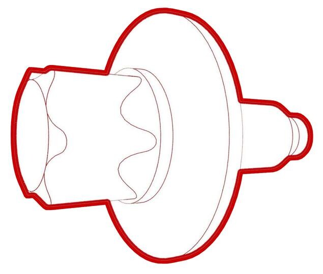
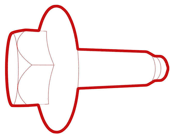
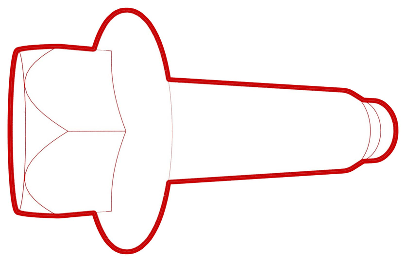
-
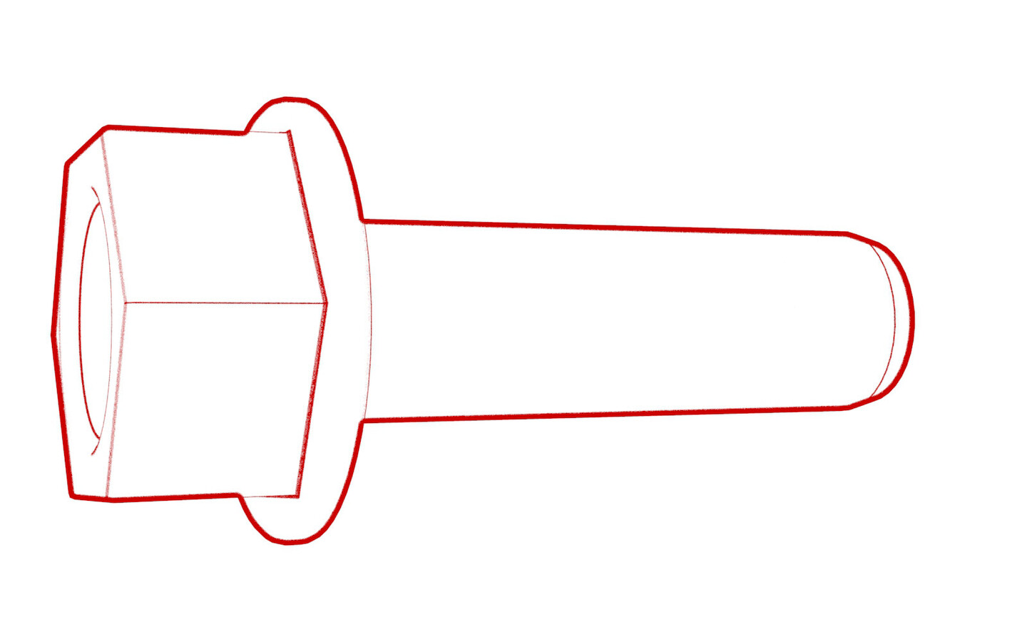
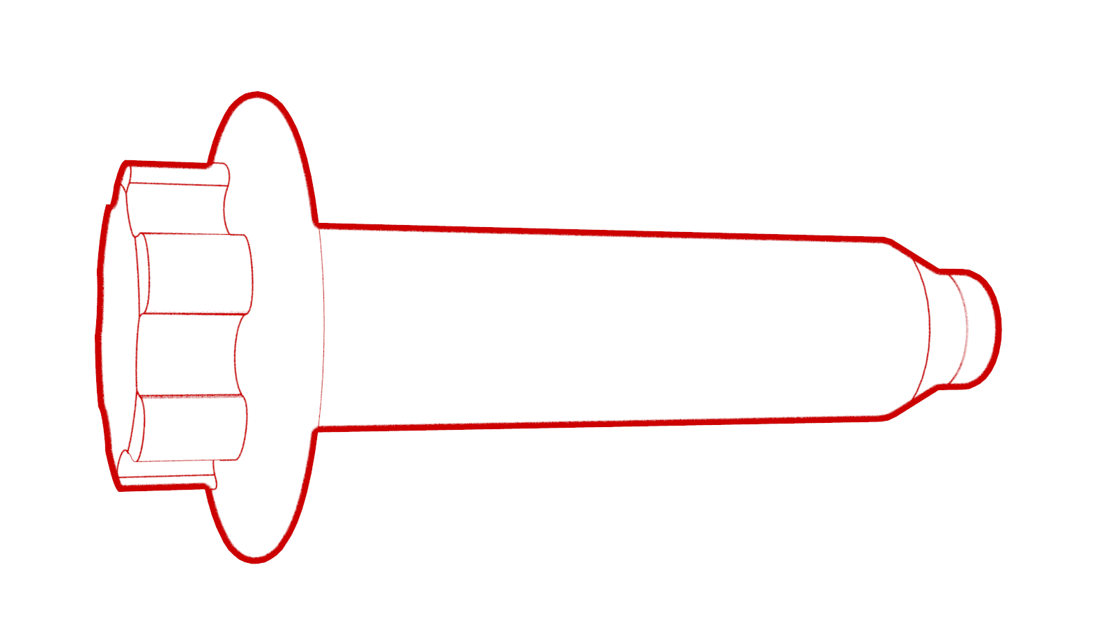
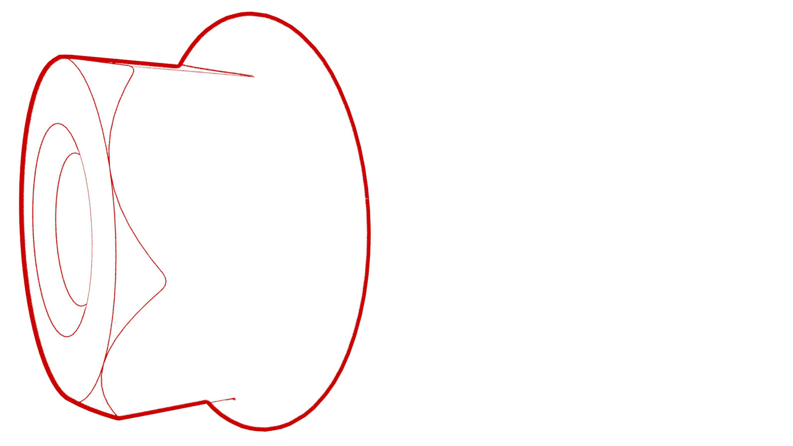
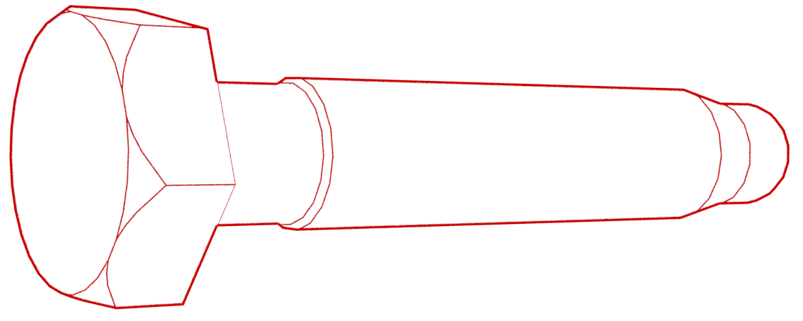
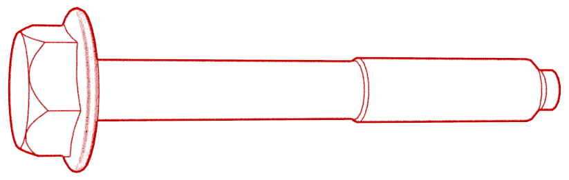
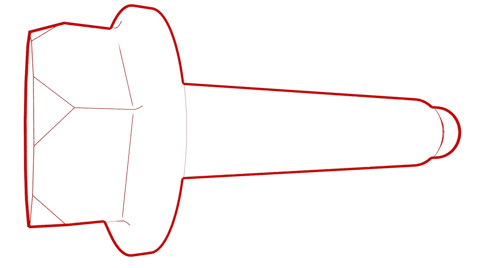
Install the HV battery alignment rods; 2 at the front of the vehicle and 2 at the HV battery near the ancillary bay.
Figure 1. RH front alignment rod shown; LH similar Figure 2. Rear alignment rods - With an assistant, position the HV battery underneath the vehicle.
-
Lower the vehicle to the HV battery, and with an assistant, align the holes with the alignment rods.
NoteDo not fully lower the vehicle onto the HV battery. The battery will still need to slightly move to install the bolts in the following steps.CAUTIONMake sure that the coolant hoses and HV harnesses are not caught on the alignment rods or sandwiched between the HV battery and the vehicle.
-
Hand-tighten the LH and RH bolts (x16) that attach the HV battery to the body.
NoteInstall the washers to the locations recorded earlier during removal.
-
Where fitted: hand-tighten the bolts
(x4) that attach the front of the HV battery to the vehicle.
-
Hand-tighten the front center bolt that attaches the HV battery to the vehicle.
- Remove the HV battery alignment rods.
-
Hand-tighten the bolts (x8) that attach the HV battery LH and RH support brackets to the vehicle.
-
Hand-tighten the bolts (x4) that attach the center portion of the HV battery through the HV battery center rail ski cover.
-
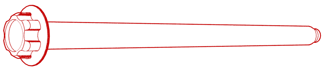
Install and hand-tighten the smaller bolts that would attach the LH and RH shear plates to the body.
NoteDo not install the shear plates at this time.
Figure 3. LH shown, RH similar -
Open the LH rear door.
CAUTIONDo not damage any components while working around this area.
-
Hand-tighten the 5th LH rear inner bolt that attaches the HV battery to the body.
NoteLift up the rear main carpet for access.
-
Hand-tighten the 4th LH inner bolt that attaches the HV battery to the body.
- Partially close, but do not latch, the LH rear door.
-
Open the LH front door.
CAUTIONDo not damage any components while working around this area.
-
Hand-tighten the 3rd LH inner bolt that attaches the HV battery to the body.
-
Hand-tighten the LH front inner bolts (x2) that attach the HV battery to the body.
- Partially close, but do not latch, the LH front door.
-
Open the RH rear door.
CAUTIONDo not damage any components while working around this area.
-
Hand-tighten the 5th RH rear inner bolt that attaches the HV battery to the body.
-
Hand-tighten the 4th RH inner bolt that attaches the HV battery to the body, if equipped.
- Partially close, but do not latch, the RH rear door.
-
Open the RH front door.
CAUTIONDo not damage any components while working around this area.
-
Hand-tighten the 3rd RH inner bolt that attaches the HV battery to the body, if equipped.
-
Hand-tighten the RH front inner bolts (x2) that attach the HV battery to the body.
- Partially close, but do not latch, the RH front door.
- With an assistant, lower the vehicle onto the HV battery completely.
-
Torque the LH and RH bolts (x16) that attach the HV battery to the vehicle.
 35 Nm (25.8 lbs-ft)
 -
Where fitted: torque the bolts (x4)
that attach the front of the HV battery to the vehicle.
 30 Nm (22.1 lbs-ft)NoteThese bolts are not present on all vehicles. Do not install these bolts if the body is patched or no hole exists.
 -
Torque the front center bolt that attaches the HV battery to the vehicle.10 Nm (7.4 lbs-ft)
-
Torque the bolts (x8) that attach the HV battery LH and RH support brackets to the vehicle.
 110 Nm (81.1 lbs-ft)
 -
Tighten the bolts (x4) that attach the center portion of the HV battery through the center ski cover.
 34 Nm (25.1 lbs-ft)
 - With an assistant, raise the vehicle, and then remove the battery table from underneath the vehicle. Set the vehicle to a comfortable working height.
- Put the support stand to support the front portion of the rear subframe.
-
Remove the smaller bolts (x2) and the larger bolt that are used to attach the LH shear plate to the vehicle.
-
Install the LH shear plate, and then install the smaller bolts (x2) that attach the shear plate to the HV battery.35 Nm (25.8 lbs-ft)
-
Install the larger bolt that attaches the shear plate to the vehicle, and then mark the bolt with a paint pen.130 Nm (95.9 lbs-ft)
-
Fasten the fir tree clips that attach the coolant hoses to the LH shear plate.
- Repeat steps 41 through 44 for the RH shear plate.
- Remove the support stand from underneath the rear subframe
-
Fully raise the handle on the HV battery rear drive unit connector of the rear drive unit to HV battery harness.
-
Install the HV connector special tool onto the HV battery rear drive unit connector.
-
Use both hands to firmly connect the HV battery rear drive unit connector of the rear drive unit to HV battery harness to the HV battery header.
CAUTIONMake sure that the connector fits the header squarely and tightly, and that both retention pins enter the handle.
- Remove the HV connector special tool from the HV battery rear drive unit connector.
-
While pressing the HV battery rear drive unit connector onto the HV battery header, fully lower the handle.
CAUTIONMake sure that the handle does not bind as it is lowered.
-
Slide the release to lock the HV battery rear drive unit connector handle in the secured position.
-
Verify that the HV battery rear drive unit connector is fully seated, and compare both sides of the connector that it is properly secured in place.
NoteAn improperly seated connector might lead to connector damage and rear drive unit problems later on.
-
Install the nuts that attach the rear drive unit HV electrical harness bracket to the HV battery.10 Nm (7.4 lbs-ft)
- Position the coolant drain under the rear RH side of the HV battery.
-
Remove the plugs from the coolant outlet hose and the powertrain return hose, immediately connect the male and female fittings, and then fasten the clip.
NotePerform a push-pull-push test on the fittings to make sure that they are secure.
- Position the coolant drain under the rear LH side of the HV battery.
-
Remove the plugs from the rear drive unit inverter inlet hose and the LH underside of the ancillary bay, immediately connect the male and female fittings, and then fasten the clip.
NotePerform a push-pull-push test on the fittings to make sure that they are secure.
- Remove the coolant drain container from underneath the vehicle.
- Install the rear HV battery skid plate, but only hand-tighten the fasteners. See Skid Plate - HV Battery - Rear (Remove and Replace).
- Torque the fasteners that attach the rear skid plate to the vehicle. See Skid Plate - HV Battery - Rear (Remove and Replace).
- Install the mid aero shield panel. See Panel - Aero Shield - Rear (Remove and Replace).
- Position the coolant drain under the front LH side of the HV battery.
-
Remove the plugs from the chiller to HV battery hose and the manifold at the LH side of the vehicle, immediately connect the male and female fittings, and then fasten the clip.
NotePerform a push-pull-push test on the fittings to make sure that they are secure.
-
Fasten the clips that attach the chiller to HV battery hose to the body.
-
Remove the plugs from the HV battery return hose at the LH side of the vehicle, immediately connect the male and female fittings, and then fasten the clip.
NotePerform a push-pull-push test on the fittings to make sure that they are secure.
- Position the coolant drain under the front RH side of the HV battery.
-
Remove the plugs from the rear powertrain supply hose at the RH side of the vehicle, immediately connect the male and female fittings, and then fasten the clip.
NotePerform a push-pull-push test on the fittings to make sure that they are secure.
-
Remove the plugs from the powertrain return hose at the RH side of the vehicle, immediately connect the male and female fittings, and then fasten the clip.
NotePerform a push-pull-push test on the fittings to make sure that they are secure.
- Remove the coolant drain from underneath the vehicle.
-
Install the bolt that attaches the ground strap to the HV battery
 10 Nm (7.4 lbs-ft)
 -
Install the clip that attaches the front drive unit ground strap to the front drive unit.
-
Install the bolt that attaches the ground strap to the front drive unit.
 6 Nm (4.4 lbs-ft)
 -
Fully raise the handle on the front drive unit HV connector of the front drive unit to HV battery harness.
-
Install the HV connector special tool onto the front drive unit HV connector.
-
Use both hands to firmly connect the front drive unit HV connector of the front drive unit to HV battery harness to the front drive unit HV header.
CAUTIONMake sure that the connector fits the header squarely and tightly, and that both retention pins enter the handle.
- Remove the HV connector special tool from the front drive unit HV connector.
-
While pressing the front drive unit HV connector onto the front drive unit HV header, fully lower the handle.
CAUTIONMake sure that the handle does not bind as it is lowered.
-
Slide the release to lock the front drive unit HV connector handle in the secured position.
-
Verify that the front drive unit HV connector is fully seated, and compare both sides of the connector that it is properly secured in place.
NoteAn improperly seated connector might lead to connector damage and front drive unit problems later on.
-
Install the bolt that attaches the front drive unit HV harness to the front drive unit.
 10 Nm (7.4 lbs-ft)
 -
Connect the A/C HV connector.
-
Connect the PTC HV electrical connector, and then install the harnesses to the bracket.
NoteThe PTC heater HV connector is only for vehicles without a heat pump. For vehicle with a heat pump, skip to the next step.
- Install the front HV battery skid plate. See Skid Plate - HV Battery - Front (Remove and Replace).
- Remove the bungee straps from the LH and RH wheel arch liners.
-
Fasten the clips along the bottom edge of the LH and RH wheel arch liners.
- Install the front aero shield panel. See Panel - Aero Shield - Front (Remove and Replace).
- Lower the vehicle fully, and chock a wheel.
- Remove the lift adapters from the body, and then install the body plugs.
-
Remove the chock, and with an assistant, push the vehicle away from the lift to a stall, and then re-chock the wheel.
CAUTIONPush the vehicle for a very short distance and at less than 1 MPH.
- Open all doors.
-
Connect the positive 12V output cable to the DCDC passthrough, install a new nut to attach the cable, and mark the nut with a green paint pen after torque.
 9 Nm (6.6 lbs-ft)CAUTIONMake sure that the rubber boot is not trapped under the cable lug or pinched between the cable lug and nut.CAUTIONMake sure the positive output cable is positioned properly and in the right direction against the plastic anti-rotation edge on the DCDC passthrough.
 - Replace the cover on the positive 12V output cable at the DCDC passthrough, and then press down to attach the cover.
- Install the DCDC ground busbar. See Busbar - DCDC Ground (Remove and Replace).
-
Install the bolts that attach the LH and RH inner 2nd row rails to the ancillary bay cover.24 Nm (17.7 lbs-ft)
- If the HV battery DC input is configured with busbars, continue to the next step, otherwise skip to step 106.
- Apply two small drops of Penetrox onto each DC input HV header terminal contact surface.
-
Install the charge port busbar connector onto the DC input HV header, and then install the bolts (x2) that attach the connector to the header.
 9 Nm (6.6 lbs-ft)
 - Perform a zero adjust of the Hioki resistance meter in preparation to measure resistances. See Resistance Meter (Zero Adjust).
- Put on the HV insulating gloves and leather over gloves.
-
Use the Hioki resistance meter to measure the resistance between the charge port busbar connector lead and the DC input HV header bolt head.
NoteThe acceptable resistance is between 0.050 mΩ (50 μΩ) and 0.195 mΩ (195 μΩ). If the measured resistance is above 0.195 mΩ (195 μΩ), there is too much resistance in the High Voltage joint. Remove the fastener, clean areas with isopropyl alcohol, install fastener back and test again.NoteIf the resistance is lower than 0.050 mΩ (50 μΩ), reposition the probes and measure again. If after 4 attempts the resistance is consistently lower than 0.050 mΩ (50 μΩ), the test has passed; continue to the next step.
- Repeat step 101 for the other charge port busbar connector lead and DC input HV header bolt head.
- Remove the HV insulating gloves and leather over gloves.
-
Install the bolt that secures the charge port busbar connector access door.
 9 Nm (6.6 lbs-ft)
 - Skip to step 111.
-
Fully raise the handle on the DC input connector of the charge port to HV battery harness.
-
Use both hands to firmly connect the DC input connector of the charge port to HV battery harness to the ancillary bay DC input header.
CAUTIONMake sure that the connector fits the header squarely and tightly.
-
While pressing the DC input connector onto the DC input header, fully lower the handle.
CAUTIONMake sure that the handle does not bind as it is lowered.
-
Slide the release to lock the DC input connector handle in the secured position.
-
Verify that the connector is fully seated, and compare both sides of the connector, that it is properly latched in place.
NoteAn improperly seated connector might lead to connector damage and charging problems later on.
- If the charge port to HV battery harness has a 3-phase connector, continue to the next step, otherwise skip to step 117.
-
Fully raise the handle on the 3-phase connector of the charge port to HV battery harness.
-
Use both hands to firmly connect the 3-phase connector of the charge port to HV battery harness to the ancillary bay 3-phase header.
CAUTIONMake sure that the connector fits the header squarely and tightly.
-
While pressing the 3-phase connector onto the 3-phase header, fully lower the handle.
CAUTIONMake sure that the handle does not bind as it is lowered.
-
Slide the release to lock the 3-phase connector handle in the secured position.
-
Verify that the connector is fully seated, and compare both sides of the connector, that it is properly latched in place.
NoteAn improperly seated connector might lead to connector damage and charging problems later on.
-
Install the clip that attaches the charge port to HV harness connector to the LH lower C-pillar.
-
Install the harness clips, and then the bolts that attach the charge port to HV battery harness bracket at the ancillary bay.
 10 Nm (7.4 lbs-ft)
 -
Install the HV cap that covers the HV harness located on the LH side of the ancillary bay.
-
Perform a cooling system vacuum
refill. See Cooling System (Vacuum Refill).
NoteThe coolant air purge will be run later in this procedure, after LV power is reconnected.
- Connect 12V power. See 12V/LV Power (Disconnect and Connect).
- Shift into Park to release the Electronic Parking Brake service mode, and then remove the wheel chock.
-
Stop the thermal fill drain routine. PROC_VCFRONT_X_STOP-THERMAL-FILL-DRAINvia Service Mode:
- Thermal ➜ Actions ➜ Stop Thermal Fill/Drain
- Thermal ➜ Coolant System ➜ Stop Coolant Fill/Drain
- Thermal ➜ Refrigerant System ➜ Stop Refrigerant Fill/Drain
- Drive Inverter ➜ Front Drive Inverter Replacement ➜ Stop Fluid Fill/Drain
- Drive Inverter ➜ Rear Drive Inverter Replacement ➜ Stop Fluid Fill/Drain
- Drive Inverter ➜ Rear Left Drive Inverter Replacement ➜ Stop Fluid Fill/Drain
- Drive Inverter ➜ Rear Right Drive Inverter Replacement ➜ Stop Fluid Fill/Drain
- Drive Unit ➜ Front Drive Unit Replacement ➜ Stop Coolant Fill/Drain
- Drive Unit ➜ Rear Drive Unit Replacement ➜ Stop Coolant Fill/Drain
-
Run the coolant air purge routine. TEST_VCFRONT_X_THERMAL-COOLANT-AIR-PURGEvia Service Mode:
- Thermal ➜ Actions ➜ Coolant Purge Stop or Coolant Purge Start
- Thermal ➜ Coolant System ➜ Coolant Purge Start
- Drive Inverter ➜ Front Drive Inverter Replacement ➜ Coolant Air Purge
- Drive Inverter ➜ Rear Drive Inverter Replacement ➜ Coolant Air Purge
- Drive Inverter ➜ Rear Left Drive Inverter Replacement ➜ Coolant Air Purge
- Drive Inverter ➜ Rear Right Drive Inverter Replacement ➜ Coolant Air Purge
- Drive Unit ➜ Front Drive Unit Replacement ➜ Coolant Air Purge
- Drive Unit ➜ Rear Drive Unit Replacement ➜ Coolant Air Purge
-
Tighten the 5th LH rear inner bolt that attaches the HV battery to the body.66 Nm (48.7 lbs-ft)NoteLift up the rear main carpet for access.
-
Tighten the 4th LH inner bolt that attaches the HV battery to the body.66 Nm (48.7 lbs-ft)
- Unfold the carpet back to its original position.
- Move the driver seat fully rearwards.
-
Tighten the 3rd LH inner HV battery bolt.66 Nm (48.7 lbs-ft)
-
Tighten the LH front inner HV battery bolts (x2) that attach the HV battery to the body.136 Nm (100.3 lbs-ft)
-
Unfold the LH front main carpet back to its original position; move the front edge down and slide back the section up to ease positioning. Install the seat electrical harness into the clip.
-
Install the clips (x3) that attach the LH front carpet to the vehicle.
- Move the driver seat fully forwards.
-
Tighten the 5th RH rear inner bolt that attaches the HV battery to the body.66 Nm (48.7 lbs-ft)
-
Tighten the 4th RH inner bolt that attaches the HV battery to the body, if equipped.66 Nm (48.7 lbs-ft)
- Unfold the RH side of the rear carpet back to its original position.
- Move the front passenger seat fully rearward.
-
Tighten the bolt that attaches the 3rd RH inner HV battery bolt to the body, if equipped.
-
Tighten the RH front inner bolts (x2) that attach the HV battery to the body.136 Nm (100.3 lbs-ft)
-
Unfold the RH front main carpet back to its original position; move the front edge down and slide back the section up to ease positioning. Install the seat electrical harness into the clip.
-
Install the clips (x4) that attach the RH front carpet to the vehicle.
- Move the front passenger seat fully forward.
-
Install the clips (x4) and hook-and-loop strips that attach the rear carpet to the vehicle.
NoteThe number of clips on newer vehicles might vary.
- Install the LH lower B-pillar trim. See Trim - B-Pillar - Lower - LH (Remove and Replace).
- Install the LH upper B-pillar trim. See Trim - B-Pillar - Upper - LH (Remove and Replace).
- Install the LH rear sill panel trim. See Trim - Sill Panel - Rear - LH (Remove and Replace).
- Install the LH 2nd row seat side bolster. See Bolster - Side - Seat - 2nd Row - LH (Remove and Replace).
- Repeat step 144 through step 147 for the RH side of the vehicle.
- Install the 2nd row lower seat cushion. See Seat Cushion - Lower - 2nd Row (Remove and Replace).
- Install the 2nd row floor mat inside the vehicle.
- Install the RH center console side panel carpet. See Side Panel - Center Console - LH (Remove and Replace).
- Install the RH front floor mat.
- Install the front passenger footwell cover. See Cover - Footwell - Passenger (LHD) (Remove and Replace).
- Install the RH lower A-pillar trim. See Trim - A-Pillar - Lower - LH (Remove and Replace).
- Install the RH middle A-pillar trim. See Trim - A-Pillar - Middle - LH (Remove and Replace).
- Install the RH instrument panel end cap. See End Cap - Instrument Panel - LH (Remove and Replace).
- Install the LH center console side panel carpet. See Side Panel - Center Console - LH (Remove and Replace).
- Install the LH front floor mat.
- Install the driver footwell cover. See Cover - Footwell - Driver (Remove and Replace).
- Install the LH lower A-pillar trim. See Trim - A-Pillar - Lower - LH (Remove and Replace).
- Install the LH middle A-pillar trim. See Trim - A-Pillar - Middle - LH (Remove and Replace).
- Install the LH instrument panel end cap. See End Cap - Instrument Panel - LH (Remove and Replace).
- Restore the driver and front passenger seats back to their original position.
- Install the cabin intake duct. See Duct - Upper - Cabin Intake (Remove and Replace).
- Install the rear underhood apron. See Underhood Apron - Rear (Remove and Replace).
- Close the hood and all four doors.
- Install the LH and RH lower rocker panel covers. See Cover - Rocker Panel - Lower - LH (Remove and Replace).