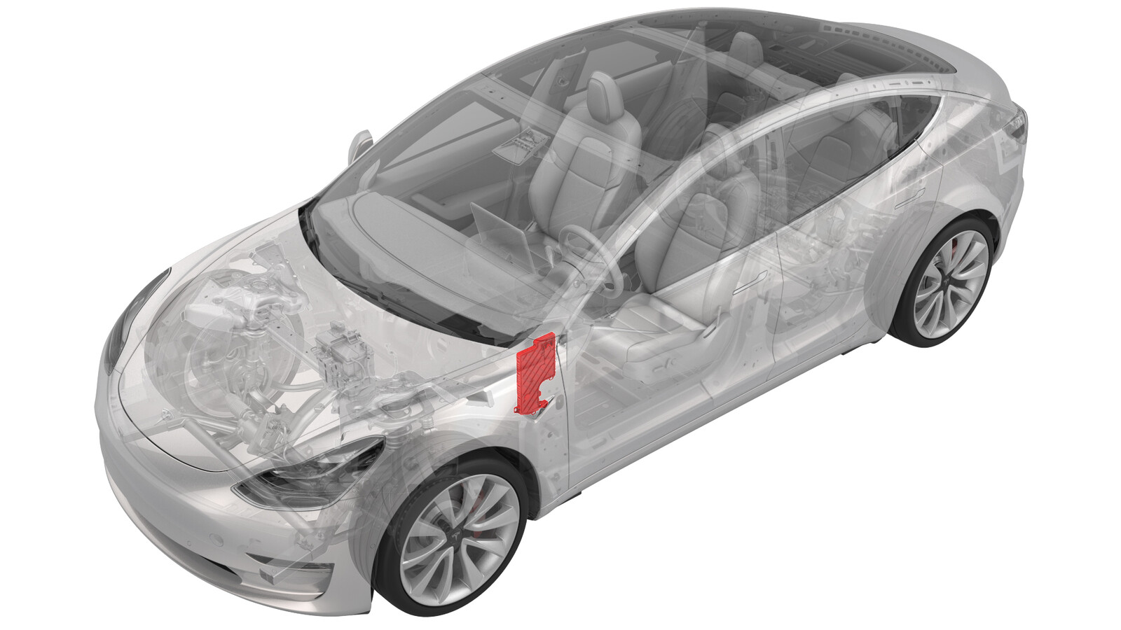
Module - Body Controller - LH (LHD)(Non-Heat Pump) (Remove and Replace)
 17152102
0.72
NOTE: Unless otherwise explicitly
stated in the procedure, the above correction code and FRT reflect all of the work
required to perform this procedure, including the linked procedures. Do not stack correction codes unless
explicitly told to do so.
NOTE: See Flat Rate
Times to learn more about FRTs and how they are created.
NOTE: See Personal Protection to make sure wearing proper PPE when
performing the below procedure. NOTE: See Ergonomic Precautions for safe and healthy working
practices.
17152102
0.72
NOTE: Unless otherwise explicitly
stated in the procedure, the above correction code and FRT reflect all of the work
required to perform this procedure, including the linked procedures. Do not stack correction codes unless
explicitly told to do so.
NOTE: See Flat Rate
Times to learn more about FRTs and how they are created.
NOTE: See Personal Protection to make sure wearing proper PPE when
performing the below procedure. NOTE: See Ergonomic Precautions for safe and healthy working
practices.
- 2023-11-13: Fixed error in routine.
Torque Specifications
| Description | Torque Value | Recommended Tools | Reuse/Replace | Notes |
|---|---|---|---|---|
| Nut that attaches the 12V cable to the LH body controller module |
 8.5 Nm (6.3 lbs-ft) |
|
Replace | |
| Nut that attaches the LH body controller module to the vehicle |
6 Nm (4.4 lbs-ft) |
|
Replace |
Remove
- Open all doors and lower all windows.
- Remove the 2nd row lower seat cushion. See Seat Cushion - Lower - 2nd Row (Remove and Replace).
- Remove the rear underhood apron. See Underhood Apron - Rear (Remove and Replace).
- Move the driver seat fully rearward.
- Disconnect 12V power. See 12V/LV Power (Disconnect and Connect).
- Remove the LH instrument panel end cap. See End Cap - Instrument Panel - LH (Remove and Replace).
- Remove the LH middle A-pillar trim. See Trim - A-Pillar - Middle - LH (Remove and Replace).
- Remove the LH lower A-pillar trim. See Trim - A-Pillar - Lower - LH (Remove and Replace).
- Remove the driver footwell cover. See Cover - Footwell - Driver (Remove and Replace).
- Remove the driver knee airbag. See Airbag - Knee - Driver (Remove and Replace).
- Remove the LH footwell duct. See Duct - Footwell - LH (LHD) (Remove and Replace).
-
Release the clip that attaches the electrical harness to the IP carrier.
-
Disconnect the clips that attach the LH front door electrical connectors to the LH body controller module.
-
Release the connector lock, and then disconnect the LH front door electrical connector from the LH body controller module.
-
Release the connector lock, and then disconnect the driver seat electrical connector from the LH body controller module.
-
Release the connector lock, and then disconnect the instrument panel electrical connector from the LH body controller module.
-
Disconnect the HVAC electrical connector from the LH body controller module.
-
Disconnect the inline electrical harness connector X909 from the LH body harness, and then separate it from the LH body controller module.
-
Remove and discard the nut that attaches the 12V power cable to the LH body controller module.
TIpUse of the following tool(s) is recommended:
- 10 mm 12-point deep socket
-
Disconnect the front wiring harness connector from the LH body controller module.
-
Disconnect the body 3 electrical connector from the LH body controller module.
-
Disconnect the body 1 electrical connector from the LH body controller module.
-
Disconnect the body 2 electrical connector from the LH body controller module.
-
Disconnect the electrical connector from the headliner electrical connector.
-
Release the electrical harness clips that attach the LH body controller module to the vehicle.
- Move the LH body harness away from the LH body controller module.
-
Release the clip that attaches the LH front door electrical harness to the LH body controller module.
-
Remove and discard the nut that attaches the LH body controller module to the vehicle.
TIpUse of the following tool(s) is recommended:
- 10 mm 12-point deep socket
-
Slide the LH body controller upwards to release the W-clip, and then move the LH body controller module out from underneath the instrument panel.
- Remove the LH body controller module from the vehicle.
-
If the LH body controller module has a shroud installed, release the clips that attach the shroud to the module.
NoteA shroud should be installed on the new body controller module even if one was not present during removal.
Install
-
Install the clip that attaches the shroud to the LH body controller module.
NoteMake sure that both clips are fully seated so that the edge of the shroud is parallel with the line on the back of the LH body controller module.CAUTIONA shroud should be installed on the body controller module even if one was not present during removal.
-
Maneuver the LH body controller module into position under the IP carrier. Align the W-clip with the body cutout, and then slide down to attach the LH body controller module to the body.
-
Install a new nut that attaches the LH body controller module onto the body.6 Nm (4.4 lbs-ft)TIpUse of the following tool(s) is recommended:
- 10 mm 12-point deep socket
-
Install the clip that attaches the shroud drain hose to the tab on the LH body controller module.
-
Install the LH front door harness clip to the LH body controller module.
-
Move the LH body harness towards the left side of the LH body controller module, and then attach the harness clips to the LH body controller module.
-
Connect the headliner electrical connector.
-
Connect the body 2 electrical connector to the LH body controller module.
-
Connect the body 1 electrical connector to the LH body controller module.
-
Connect the body 3 electrical connector to the LH body controller module.
-
Connect the front wiring connector to the LH body controller module.
-
Install new nut that attaches the 12V power cable to the LH body controller module.8.5 Nm (6.3 lbs-ft)TIpUse of the following tool(s) is recommended:
- 10 mm 12-point deep socket
-
Connect the inline electrical connector X909 to the LH body harness, and then clip it to the LH body controller module.
-
Connect the HVAC electrical connector to the LH body controller module , and then engage the connector lock.
NoteEnsure the electrical connector is fully seated.
-
Install the instrument panel electrical connector to the LH body controller module, and then engage the connector lock.
NoteEnsure the electrical connector is fully seated.
-
Connect the driver seat electrical connector to the LH body controller module, and then engage the connector lock.
NoteEnsure the electrical connector is fully seated.
-
Connect the LH front door electrical connector to the LH body controller module, and then engage the connector lock.
NoteEnsure the electrical connector is fully seated.
-
Connect the clips that attach the LH front door electrical connectors to the LH body controller module.
-
Connect the electrical harness clip onto the IP carrier.
- Install the LH footwell duct. See Duct - Footwell - LH (LHD) (Remove and Replace).
- Install the driver knee airbag. See Airbag - Knee - Driver (Remove and Replace).
- Install the driver footwell cover. See Cover - Footwell - Driver (Remove and Replace).
- Install the LH lower A-pillar trim. See Trim - A-Pillar - Lower - LH (Remove and Replace).
- Install the LH middle A-pillar trim. See Trim - A-Pillar - Middle - LH (Remove and Replace).
- Install the LH instrument panel end cap. See End Cap - Instrument Panel - LH (Remove and Replace).
-
Connect 12V power. See 12V/LV Power (Disconnect and Connect).
CAUTIONDo not power on the climate control system until this procedure has been fully completed.
- Install the rear underhood apron. See Underhood Apron - Rear (Remove and Replace).
- Install the 2nd row lower seat cushion. See Seat Cushion - Lower - 2nd Row (Remove and Replace).
- Perform a service CAN redeploy. See Software Reinstall - Toolbox.
- Sit in the front passenger seat and close the RH front door.
- Perform the following routine using Service Mode or Toolbox (see 0005 - Service Modes): PROC_CONTROLLER_LEFT_POST-REPLACEMENT-PROCEDUREvia Service Mode Plus:Left Controller ➜ Left Controller Post Replacement ➜ Left Controller Post Replacement Procedurevia Toolbox:(link)
- Inform the customer that their liftgate opening height settings have been reset and to refer to the owner's manual for instructions on setting the liftgate opening height.