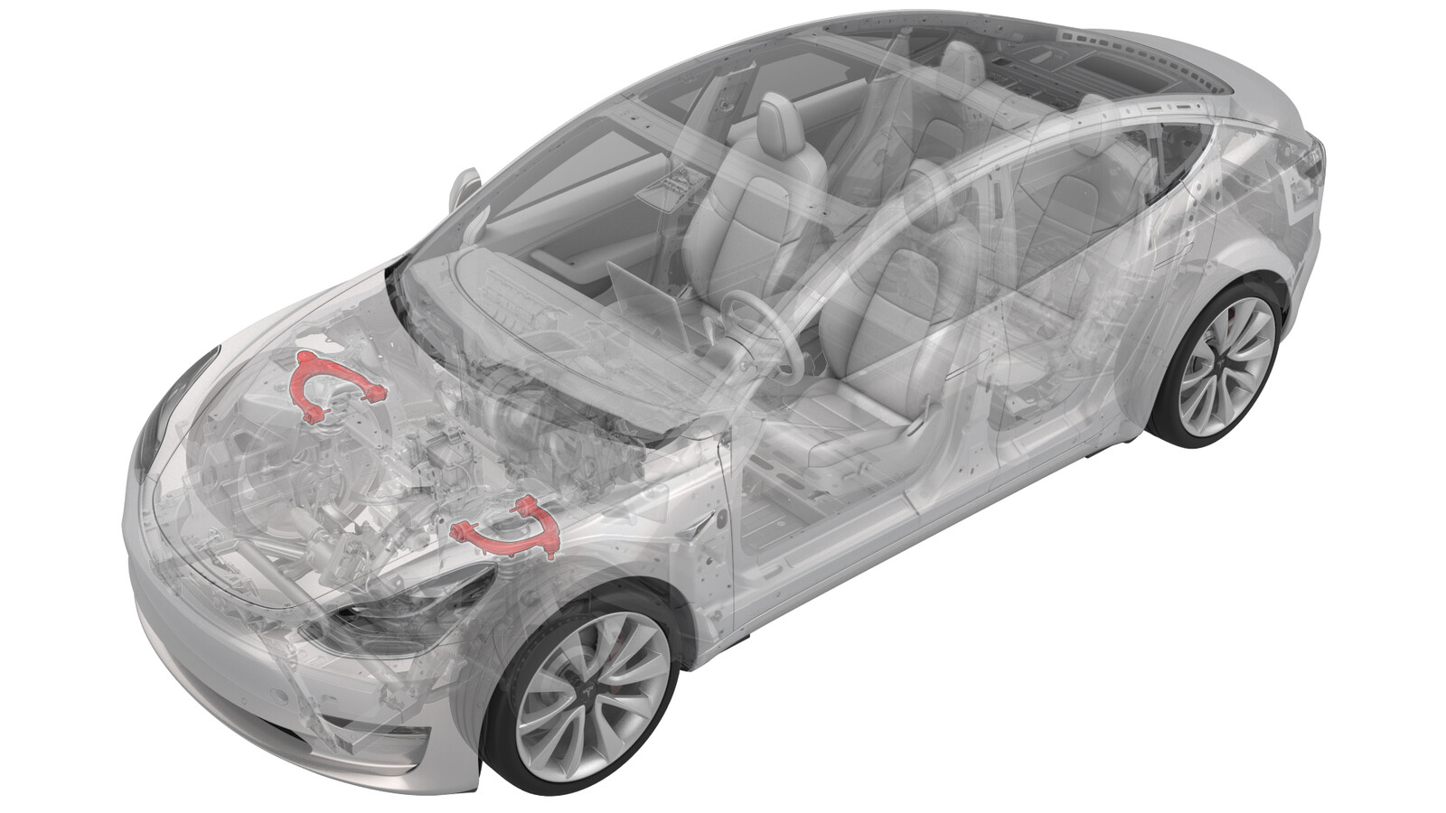
Control Arm - Upper - Front - LH (Remove and Replace)
 Correction code
31014002
0.72
NOTE: Unless otherwise explicitly
stated in the procedure, the above correction code and FRT reflect all of the work
required to perform this procedure, including the linked procedures. Do not stack correction codes unless
explicitly told to do so.
NOTE: See Flat Rate
Times to learn more about FRTs and how they are created.
NOTE: See Personal Protection to make sure wearing proper PPE when
performing the below procedure. NOTE: See Ergonomic Precautions for safe and healthy working
practices.
Correction code
31014002
0.72
NOTE: Unless otherwise explicitly
stated in the procedure, the above correction code and FRT reflect all of the work
required to perform this procedure, including the linked procedures. Do not stack correction codes unless
explicitly told to do so.
NOTE: See Flat Rate
Times to learn more about FRTs and how they are created.
NOTE: See Personal Protection to make sure wearing proper PPE when
performing the below procedure. NOTE: See Ergonomic Precautions for safe and healthy working
practices.
- 2026-02-27: Deleted illustrations on headlight adjustment, added photo showing the sensor arm being zip-tied to the ride height sensor bracket.
- 2025-12-29: Clarified part numbers with which to use 145399-E1-A spacer tool.
- 2025-12-09: Added part numbers 1188321-XX-X and 1188326-XX-X.
- 2023-09-21: Added tool information on FUCA tool spacer (1450399-E1-A) for later part revisions of the FUCA (1288321-XX-X and 1288326-XX-X).
Equipment:
- 1450399-00-A Tool, FUCA Ride Height, Model 3
- 1450399-E1-A FUCA Tool Spacer (use in conjunction with 1450399-00-A for later revisions of the FUCA, part numbers 1288321-XX-X, 1288326-XX-X, 1188321-XX-X and 1188326-XX-X).
Torque Specifications
| Description | Torque Value | Recommended Tools | Reuse/Replace | Notes |
|---|---|---|---|---|
| Smaller bolts that attach the LH front upper control arm mount to the body |
 35 Nm (25.8 lbs-ft) |
|
Reuse | |
| Larger bolts that attach the LH front upper control arm mount to the body |
62 Nm (45.7 lbs-ft) |
|
Reuse | |
| Bolt that attaches the LH front ride height sensor arm to the upper control arm |
8 Nm (5.9 lbs-ft) |
|
Reuse | |
| Nyloc nut that attaches the front stabar link to the front strut |
98 Nm (72.3 lbs-ft) |
|
Replace (1111543-00-A-) | |
| Nuts that attach the LH front upper control arm to the to knuckle |
56 Nm (41.3 lbs-ft) |
|
Replace | |
| Bolts securing LH upper control arm to FUCA mount |
50 Nm (36.9 lbs-ft) |
|
Reuse |
Remove
- Inspect the vehicle for abnormal tire wear that might indicate the need for a wheel alignment. Note any findings.
-
Loosen the LH front wheel
lug nuts.
CAUTIONUse a 6 point socket. Do not use a 12 point socket or a specialty socket.
- Raise and support the vehicle. See Raise Vehicle - 2 Post Lift.
- Remove the rear underhood apron. See Underhood Apron - Rear (Remove and Replace).
- Remove the cabin intake duct. See Duct - Upper - Cabin Intake (Remove and Replace).
- Remove the hood latch cover. See Cover - Hood Latch (Remove and Replace).
- Remove the underhood storage unit. See Underhood Storage Unit (Remove and Replace).
-
Release the rear clip that
attaches the LH shock tower cover to the vehicle, and then swivel the shock
tower cover aside.
-
Remove the LH clip that
attaches the cowl screen panel to the vehicle.
Figure 1. Model 3 shown; Model Y similar -
Lift the cowl screen panel
and mark the positions of the LH front upper control arm mount bolts
(x4).
Figure 2. Model 3 shown; Model Y similar -
Remove the smaller bolts
that attach the spring and damper assembly to the shock tower.
TIpUse of the following tool(s) is recommended:
- 13 mm socket
- Flex head ratchet/flex head torque wrench
Figure 3. Model 3 shown; Model Y similar -
Remove the larger bolts that
attach the spring and damper assembly to the shock tower.
TIpUse of the following tool(s) is recommended:
- 15 mm socket
- Flex head ratchet/flex head torque wrench
Figure 4. Model 3 shown; Model Y similar - Raise the vehicle to a comfortable working height.
- Remove the LH front wheel. See Wheel Assembly (Remove and Install).
-
Release the clips (x2) that attach the wheel speed sensor harness to the LH
front upper control arm, and then set the harness aside.
Figure 5. Model 3 shown; Model Y similar -
If the vehicle is equipped with a ride height sensor:
-
Remove and discard the nut
that attaches the stabilizer bar link to the LH front spring and damper
assembly, and then move the link aside.
NoteCounter-hold the ball joint while loosening the nut.TIpIf needed, use a pry bar to release the end link.TIpUse of the following tool(s) is recommended:
- 18 mm combination wrench
- Torx T40 socket
- Cordless Ratchet/Impact Driver
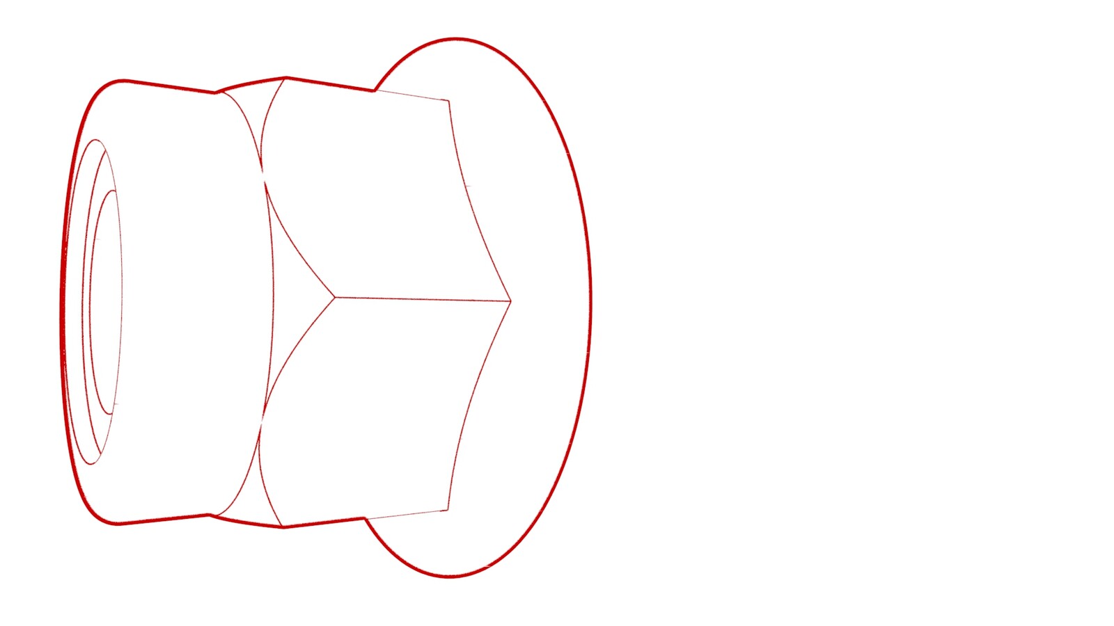
Figure 8. Model 3 shown; Model Y similar -
Remove the bolt and nut that
attach the upper control arm to the knuckle, and then discard the nut.
NoteCompress the upper control arm ball joint downwards to help release the bolt.TIpUse of the following tool(s) is recommended:
- 15 mm combination wrench
- Torx T50 socket
- Cordless Ratchet/Impact Driver
Figure 9. Model 3 shown; Model Y similar -
Pull the LH front spring and damper assembly outboard so that the front
upper control arm mount clears the wheel arch liner.
TIpHold the front upper control arm mount and use thumbs to push the wheel arch liner past the mount.WarningThe video(s) included in this procedure are meant as an overview for supplemental purposes only. Follow all of the steps listed in the procedure to avoid damage to components and/or personal injury.
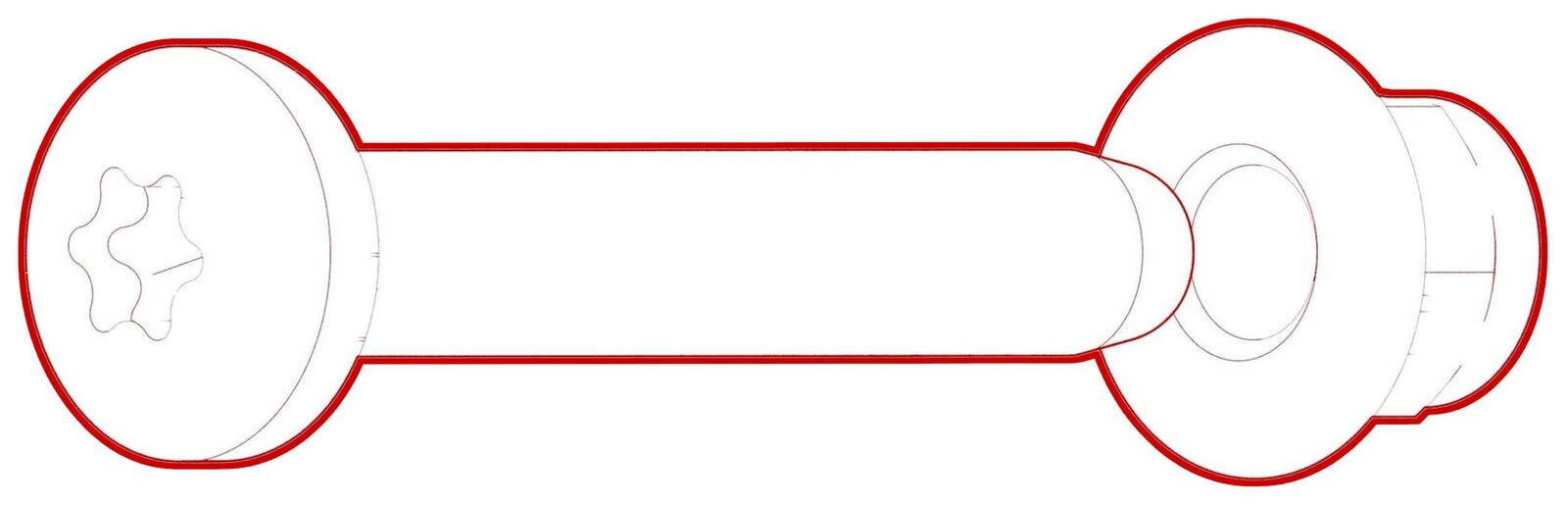
Figure 10. Model 3 shown; Model Y similar Figure 11. Model 3 shown; Model Y similar -
Remove the bolts that attach
the LH front upper control arm to the front upper control arm mount.
TIpUse of the following tool(s) is recommended:
- 13 mm deep socket
- Cordless Ratchet/Impact Driver
-
Remove the LH front upper
control arm from the front upper control arm mount.
Install
-
Position the LH front upper
control arm into the front upper control arm mount, and then install and
hand-tighten the bolts (x2) that attach the control arm to the mount.
-
Install the FUCA ride height
tool onto the front upper control arm mount at the rear outer mounting
hole.
NoteFor FUCA part revisions 1288321-XX-X and 1288326-XX-X, use 1450399-E1-A (FUCA Tool Spacer) in conjunction with 1450399-00-A (Tool, FUCA Ride Height, Model 3).NoteIf an updated FUCA ride height tool for a newer FUCA is not available, use two pocket rulers to set the ride height:
- Lay a pocket ruler across the upper flat surface of the front upper control arm.
- Use a second
pocket ruler to measure 60 mm between the front upper control
arm mount threaded hole and the first pocket ruler.
-
Hold the front upper control
arm against the plate of the FUCA ride height tool and tighten the bolts
(x2) that attach the LH front upper control arm to the front upper control
arm mount.
 50 Nm (36.9 lbs-ft)CAUTIONTo prevent personal injury when torquing bolts and simultaneously holding components in position, pay extra attention to the angle and trajectory of the tool used.NoteAfter tightening, check the measurement again and adjust if necessary.TIpUse of the following tool(s) is recommended:
- 13 mm deep socket
- Cordless Ratchet/Impact Driver
- Remove the FUCA ride height tool from the front upper control arm mount.
-
Move the LH coil spring
module and front upper control arm mount assembly into position, making sure
the control arm mount bolt holes are aligned with the bolt holes on the
body.
Figure 12. Model 3 shown; Model Y similar. Wheel arch liner removed for clarity. - Lower the vehicle so that the shock tower is accessible. If the lift cannot be locked in that position, set the lift to its lowest lockable position and use a step stool to gain access to the shock tower.
-
Install the larger bolts
that attach the spring and damper assembly to the shock tower.
 62 Nm (45.7 lbs-ft)NoteLine up the bolts with the paint marks made during removal.TIpUse of the following tool(s) is recommended:
- 15 mm socket
- Flex head ratchet/flex head torque wrench
- Cordless Ratchet/Impact Driver
- Step stool
Figure 13. Model 3 shown; Model Y similar -
Install the smaller bolts
that attach the spring and damper assembly to the shock tower.
 35 Nm (25.8 lbs-ft)NoteLine up the bolts with the paint marks made during removal.TIpUse of the following tool(s) is recommended:
- 13 mm socket
- Flex head ratchet/flex head torque wrench
- Cordless Ratchet/Impact Driver
- Step stool
Figure 14. Model 3 shown; Model Y similar -
Install a new nut that
attaches the stabilizer bar link to the LH front spring and damper
assembly.
 98 Nm (72.3 lbs-ft)NoteCounter-hold the ball joint while torquing the nut.TIpIf needed, use a pry bar to help position the end link.TIpUse of the following tool(s) is recommended:
- Torx T40 socket
- 18 mm combination wrench
- 6 in extension
- Cordless Ratchet/Impact Driver
Figure 15. Model 3 shown; Model Y similar -
Install the bolt and new nut
that attach the upper control arm to the knuckle.
 56 Nm (41.3 lbs-ft)TIpUse of the following tool(s) is recommended:
- 15 mm combination wrench
- Torx T50 socket
- Cordless Ratchet/Impact Driver
Figure 16. Model 3 shown; Model Y similar -
Depending on the vehicle's
configuration, choose one of the following:
- If the vehicle is not equipped with a ride height sensor, go to step 17.
- If the vehicle is equipped with a ride height sensor, and the new upper control arm has a mount for the ride height sensor, go to step 12.
- If the vehicle is equipped with a ride height sensor, but the new upper control arm does not have a mount for the ride height sensor, go to step 15.
-
Install the ride height
sensor arm onto the upper control arm, and then install the bolt that
attaches the sensor arm to the upper control arm.
NoteHold the ball stud in place with a wrench.TIpUse of the following tool(s) is recommended:
- 12 mm combination wrench
- 10 mm socket
Figure 17. Model 3 shown; Model Y similar -
Connect the LH front ride
height sensor connector.
Figure 18. Model 3 shown; Model Y similar - Go to step 17.
- Remove the extended ride height sensor arm from the ride height sensor, and then discard the extended arm.
-
Fold the ride height sensor
arm backwards, and then use a zip tie to fasten the sensor arm to the ride
height sensor.
-
Install the clips (x2) that
attach the wheel speed sensor harness to the LH front upper control
arm.
Figure 19. Model 3 shown; Model Y similar - Position the LH front wheel on the vehicle and hand-tighten the lug nuts (x5) that attach the wheel to the vehicle.
- Lower the vehicle until the tires are touching the ground. See Raise Vehicle - 2 Post Lift.
- Torque the LH front wheel lug nuts. See Wheel Assembly (Remove and Install).
- Install the wheel cap, if equipped. See Cap - Wheel (Remove and Replace).
-
Install the LH clip that
attaches the cowl screen panel to the vehicle.
Figure 20. Model 3 shown -
Move the LH shock tower
cover back into position, and then install the rear clip that attaches the
cover to the vehicle.
Figure 21. Model 3 shown - Install the underhood storage unit. See Underhood Storage Unit (Remove and Replace).
- Install the hood latch cover. See Cover - Hood Latch (Remove and Replace).
- Install the cabin intake duct. See Duct - Upper - Cabin Intake (Remove and Replace).
- Install the rear underhood apron. See Underhood Apron - Rear (Remove and Replace).
- Close the hood.
- Refer to the Alignment Requirement tables to determine whether an EPAS alignment check (EC) or four wheel alignment check (AC) is necessary. If performed, add the alignment check/adjust correction code as a separate activity to the SV. See Alignment Requirement - Suspension.
- Only if the ride height sensor has been disconnected as instructed in step 15, perform the following steps:
- Enter Service Mode Plus. See Service Mode Plus.
-
On the touchscreen, under
Vehicle Info, touch , tap Run, and
allow the routine to complete.
- If the Leveling System was already set to use the Virtual Pitch Sensor, as a result of a rear height sensor being disabled in an earlier stage, do not adjust the headlights
- After converting the Leveling System to Virtual Pitch Sensor, adjust the headlights in the next step.
- Adjust the headlights: