Knuckle - Suspension - Rear - LH (Remove and Replace)
 Correction code
31030102
0.96
NOTE: Unless otherwise explicitly
stated in the procedure, the above correction code and FRT reflect all of the work
required to perform this procedure, including the linked procedures. Do not stack correction codes unless
explicitly told to do so.
NOTE: See Flat Rate
Times to learn more about FRTs and how they are created.
NOTE: See Personal Protection to make sure wearing proper PPE when
performing the below procedure. NOTE: See Ergonomic Precautions for safe and healthy working
practices.
Correction code
31030102
0.96
NOTE: Unless otherwise explicitly
stated in the procedure, the above correction code and FRT reflect all of the work
required to perform this procedure, including the linked procedures. Do not stack correction codes unless
explicitly told to do so.
NOTE: See Flat Rate
Times to learn more about FRTs and how they are created.
NOTE: See Personal Protection to make sure wearing proper PPE when
performing the below procedure. NOTE: See Ergonomic Precautions for safe and healthy working
practices.
- 2025-05-01: Added note about ball joint replacement.
- 2024-12-11: Made correction to Note that mentions one/both rear lower fore links.
- 2023-11-17: Mentioned correction code 31030312 for scenarios where both rear fore links are replaced as well.
- 2023-11-14: Mentioned correction code 31030302, which is to be added when one rear fore link is replaced as well.
Equipment:
- 1135103-00-A Tool, Spring Compressor, Hook, Model 3
- 1062500-00-A Card, Magnetic Field Viewer
- 1137855-00-A TOOL, REAR RIDE HEIGHT TORQUE, MODEL 3
- 1081765-00-A 3/4 TON UNDERHOIST STAND
- 1459409-00-A ADAPTER, HUB JACK, MODEL 3
Remove
-
Inspect the tires for
abnormal wear.
NoteNote any abnormal tire wear that could indicate the need for an alignment.
- Open the LH front door.
- Place the vehicle into "Towing" mode.
- Raise and support the vehicle. See Raise Vehicle - 2 Post Lift.
- Loosen the LH rear wheel lug nuts, but do not remove the wheel at this time. See Wheel Assembly (Remove and Install).
-
Loosen the LH rear halfshaft
nut.
- Remove the LH rear wheel. See Wheel Assembly (Remove and Install).
-
Disconnect the electrical
wiring harness connector from the parking brake.
-
Remove and discard the bolts
(x2) that attach the LH rear caliper to the LH rear knuckle, remove the
caliper from the knuckle, and allow the caliper to hang from an S-hook.
 83 Nm (61.2 lbs-ft)NoteHand-tighten the lug nut to secure the rotor on early production vehicles.TIpUse of the following tool(s) is recommended:
- External Torx E18
-
Remove and discard the nut,
and remove the washer that attach the LH halfshaft to the hub
assembly.
-
Remove the bolt that
attaches the brake rotor to the hub.
NoteEarly production vehicles may not be equipped with a bolt securing the rotor.
- Install the hub puller onto the LH rear rotor, and then install and hand-tighten the puller washers (x5) and the lug nuts (x5) onto the rotor studs.
-
Use the hub puller to free
the halfshaft from the hub splines.
NoteThe halfshaft is removed at a later step.
- Remove the lug nuts (x5) and the puller washers (x5) from the LH rear rotor studs, and then remove the hub puller from the rotor.
-
Remove the LH rear brake
rotor from the vehicle.
CAUTIONPlace the rotor hat down to prevent damage to the rotor face.
-
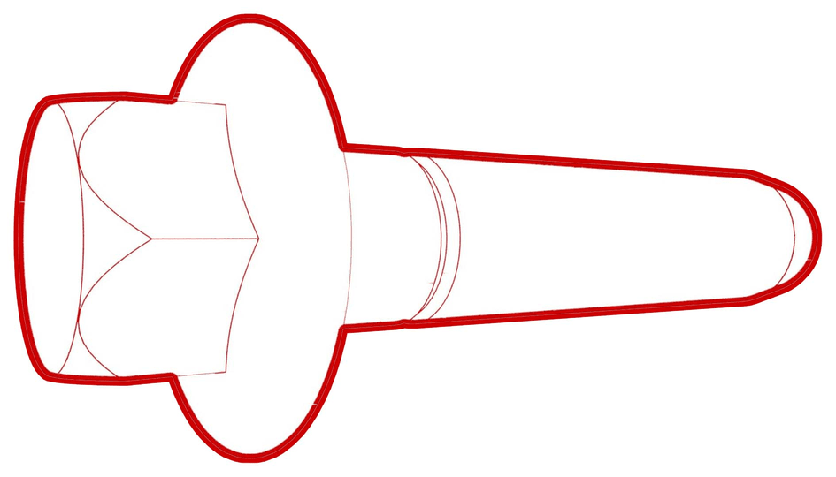
Remove the bolts (x3) that
attach the LH rear hub to the knuckle, and then remove the hub from the
axle.
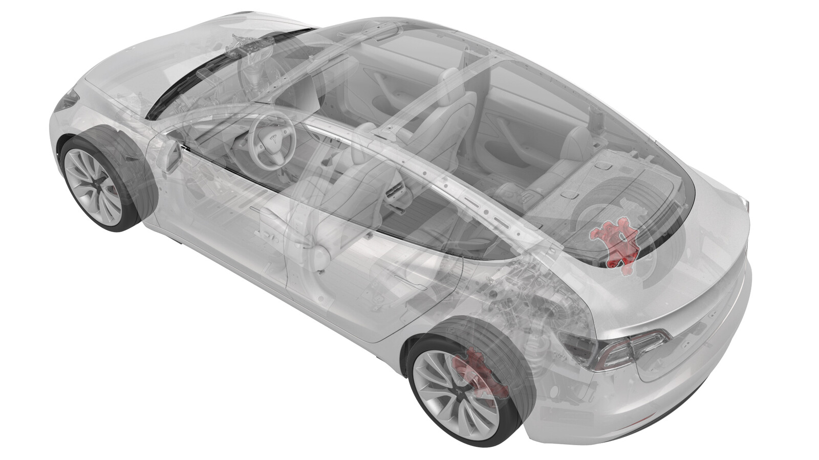
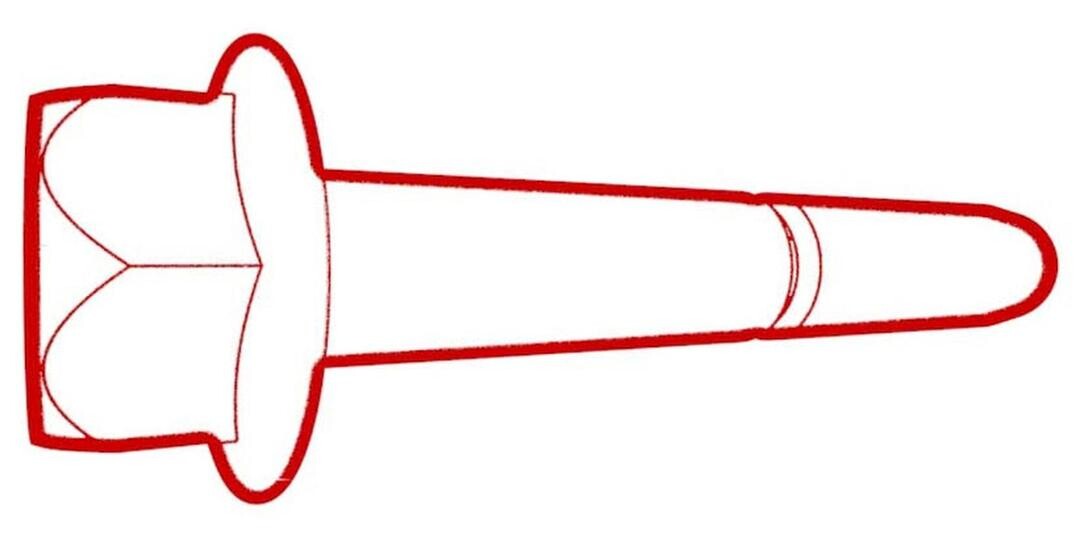
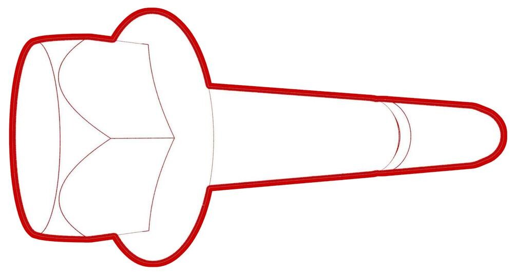
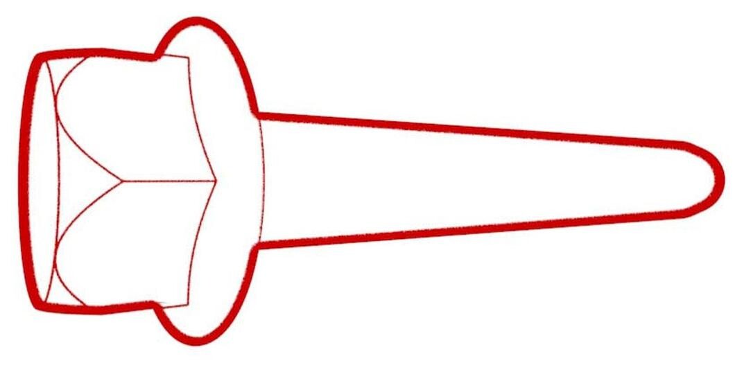
Figure 1. Halfshaft hidden for clarity -
Remove the bolts (x3) that
attach the LH rear brake dust shield to the knuckle, and then remove the
dust shield from the vehicle.
-
Remove the bolt that
attaches the rear LH ABS wheel speed sensor to the knuckle.
-
Release the clip and remove
the grommet that attach the rear LH ABS wheel speed sensor cable to the rear
knuckle and bracket.
- Remove the LH rear suspension cover. See Cover - Rear Suspension - LH (Remove and Replace).
-
Use the support stand to
raise the LH rear suspension.
-
Remove and discard the nut
that attaches the LH stabilizer bar link to the LH rear suspension knuckle,
and then remove the link from the knuckle.
NoteCounter-hold the ball joint with a 5 mm hex wrench.
-
Remove the bolt and nut that
attach the LH rear upper aft link to the LH rear suspension knuckle.
 134 Nm (98.8 lbs-ft)
 134 Nm (98.8 lbs-ft)
 -
Remove the bolt and nut that
attach the LH rear upper fore link to the LH rear suspension knuckle.
 76 Nm (56.0 lbs-ft)
 76 Nm (56.0 lbs-ft)
 -
Remove the bolt and nut that
attach the LH toe link to the LH rear suspension knuckle.
 76 Nm (56.0 lbs-ft)
 76 Nm (56.0 lbs-ft)
 -
Remove the bolt and nut that
attach the LH rear lower fore link to the LH rear suspension knuckle.
 76 Nm (56.0 lbs-ft)
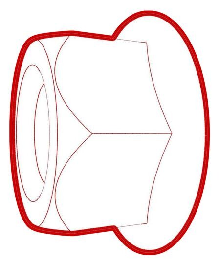 76 Nm (56.0 lbs-ft)
 -
Remove the bolt and nut that
attach the LH rear aft lower link to the LH rear suspension knuckle.
 115 Nm (84.8 lbs-ft)
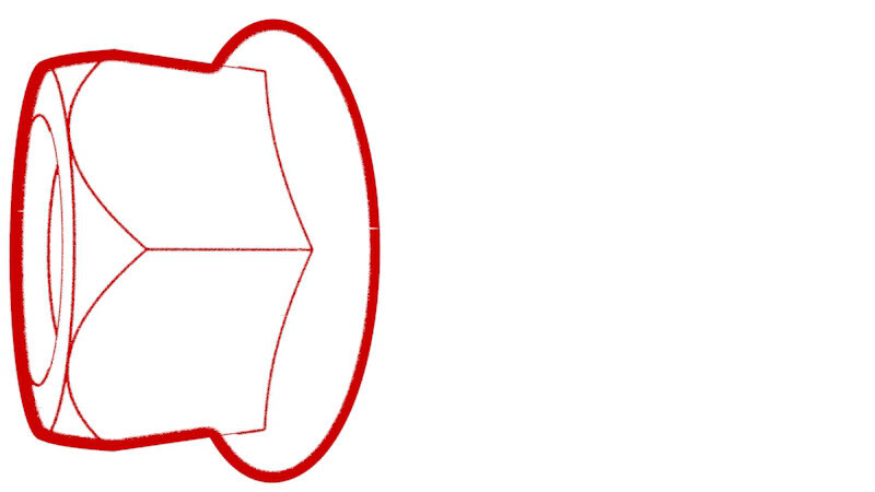 115 Nm (84.8 lbs-ft)
 -
Remove the LH rear
suspension knuckle from the vehicle.
Install
- Position the LH rear suspension knuckle on the rear suspension.
-
Install and hand-tighten the
bolt and nut that attach the LH rear aft lower link to the LH rear
suspension knuckle.
-
Install and hand-tighten the
bolt and nut that attach the LH rear lower fore link to the LH rear
suspension knuckle.
-
Install and hand-tighten the
bolt and nut that attach the LH toe link to the LH rear suspension
knuckle.
-
Install and hand-tighten the
bolt and nut that attach the LH rear upper fore link to the LH rear
suspension knuckle.
-
Install and hand-tighten the
bolt and nut that attach the LH rear upper aft link to the LH rear
suspension knuckle.
-
Install and hand-tighten the
nut that attaches the LH stabilizer bar link to the LH rear suspension
knuckle.
NoteCounter-hold the ball joint with a 5 mm hex wrench.
- Remove the support stand from underneath the LH rear suspension.
-
Install the clip and grommet
that attach the rear LH ABS wheel speed sensor cable to the rear knuckle and
bracket.
-
Install the bolt that
attaches the rear LH ABS wheel speed sensor to the knuckle.
-
Position the LH rear brake
dust shield on the knuckle, and then install the bolts that attach the dust
shield to the knuckle.8 Nm (5.9 lbs-ft)
-
Position the LH rear hub
into the knuckle, and then install the bolts that attach the hub to the
vehicle.
 85 Nm (62.7 lbs-ft)
 -
Install only the axle nut onto the
halfshaft, and then use a ratchet and socket to manually tighten the nut to pull the
halfshaft into the hub until it seats.
NoteDo not use power tools to tighten the nut as it might strip the threads.
-
Remove the axle nut from the halfshaft,
install a new washer onto the halfshaft, and then reinstall the axle nut hand
tightened.
NoteThe axle nut is torqued in a later step.
- Position the LH rear brake rotor onto the vehicle.
-
Install new bolts that
attach the LH rear caliper bracket to the knuckle.
 83 Nm (61.2 lbs-ft)
 -
Connect the electrical
harness to the LH rear brake caliper connector.
-
Install the hub jack adapter
onto the LH rear hub and hand-tighten the lug nuts.
-
Use an underhoist stand to
support the hub jack adapter.
-
Locate the rear ride height
torque tool insertion point in the subframe, and then insert the rear ride
height torque gauge to verify that the rear suspension is set to ride height
specifications. Adjust the support stand or spring compressor tool, if
necessary.
NoteThe suspension is at the simulated ride height when the top of the tool touches the subframe and the lower part of the tool interfaces with the lower control arm.TIpUse of the following tool(s) is recommended:
- 1137855-00-A TOOL, REAR RIDE HEIGHT TORQUE, MODEL 3
-
Measure the distance between
the bottom of the quarter panel to the center of the rear axle to make sure
that the rear suspension is set to ride height: The distance should measure
378 mm.
-
Tighten the bolt and nut
that attach the LH rear aft lower link to the LH rear suspension knuckle.
Mark the bolt with a paint pen.115 Nm (84.8 lbs-ft)115 Nm (84.8 lbs-ft)
-
Tighten the bolt and nut
that attach the LH rear lower fore link to the LH rear suspension knuckle.
Mark the bolt with a paint pen.76 Nm (56.0 lbs-ft)76 Nm (56.0 lbs-ft)
-
Tighten the bolt and nut
that attach the LH toe link to the LH rear suspension knuckle. Mark the bolt
with a paint pen.76 Nm (56.0 lbs-ft)76 Nm (56.0 lbs-ft)
-
Tighten the bolt and nut
that attach the LH rear upper fore link to the LH rear suspension knuckle.
Mark the bolt with a paint pen.76 Nm (56.0 lbs-ft)76 Nm (56.0 lbs-ft)
-
Tighten the bolt and nut
that attach the LH rear upper aft link to the LH rear suspension knuckle.
Mark the bolt with a paint pen.134 Nm (98.8 lbs-ft)134 Nm (98.8 lbs-ft)
-
Tighten the nut that
attaches the LH stabilizer bar link to the LH rear suspension knuckle. Mark
the bolt with a paint pen.55 Nm (40.6 lbs-ft)
-
Remove the underhoist stand
from underneath the LH rear suspension.
-
Remove the lug nuts that
attach the hub jack adapter, and then remove the hub jack adapter from the
vehicle.
-
Install the bolt that
attaches the brake rotor to the hub.
 5 Nm (3.7 lbs-ft)
 - Install the LH rear suspension cover. See Cover - Rear Suspension - LH (Remove and Replace).
- Install the LH rear wheel. See Wheel Assembly (Remove and Install).
-
Tighten the LH rear axle
nut.300 Nm (221.2 lbs-ft)
- Refer to the Alignment Requirement tables to determine whether an EPAS alignment check (EC) or four wheel alignment check (AC) is necessary. If performed, add the alignment check/adjust correction code as a separate activity to the SV. See Alignment Requirement - Suspension.