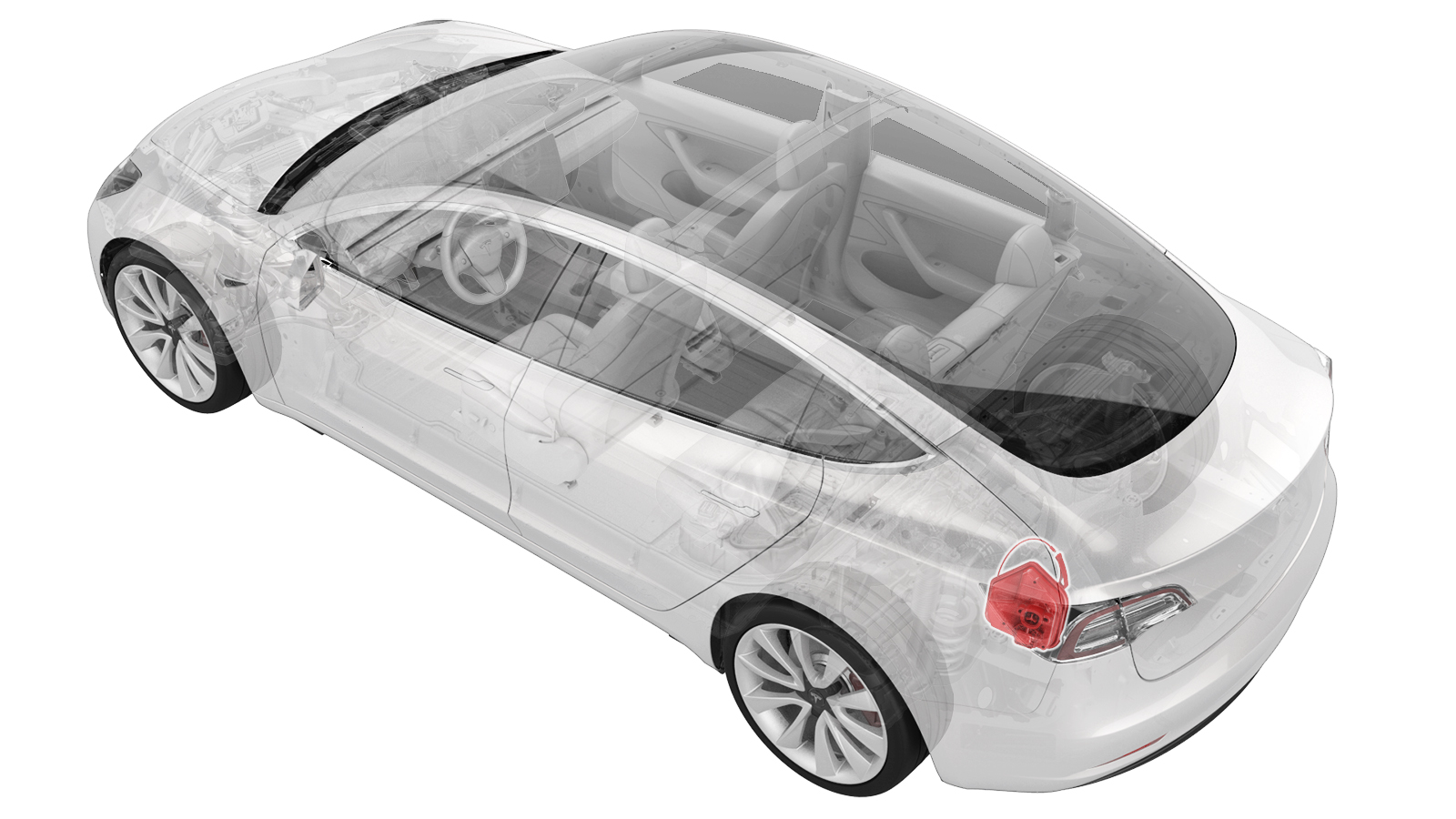
Charge Port (Busbar Type) (NACS) (Remove and Replace)
 Correction code
44011602
0.54
NOTE: Unless otherwise explicitly
stated in the procedure, the above correction code and FRT reflect all of the work
required to perform this procedure, including the linked procedures. Do not stack correction codes unless
explicitly told to do so.
NOTE: See Flat Rate
Times to learn more about FRTs and how they are created.
NOTE: See Personal Protection to make sure wearing proper PPE when
performing the below procedure. NOTE: See Ergonomic Precautions for safe and healthy working
practices.
Correction code
44011602
0.54
NOTE: Unless otherwise explicitly
stated in the procedure, the above correction code and FRT reflect all of the work
required to perform this procedure, including the linked procedures. Do not stack correction codes unless
explicitly told to do so.
NOTE: See Flat Rate
Times to learn more about FRTs and how they are created.
NOTE: See Personal Protection to make sure wearing proper PPE when
performing the below procedure. NOTE: See Ergonomic Precautions for safe and healthy working
practices.
- 2026-03-12: Added note to reset the charge port ECU if vehicle is not charging as expected after replacement.
- 2023-12-07: Corrected Hioki resistance value and added charge port release cable clip image.
- 2023-10-27: Update charge port to body bolt torque to 9 Nm.
- 2023-10-10: Add a caution to not manually close the charge port door.
- 2023-05-24: Removed the vehicle electrical isolation procedure.
- 2023-04-06: Added Hioki resistance meter to tool list.
Equipment:
- 1076927-00-A Hioki RM 3548
- 1076928-00-A Test Probes - Hioki 9461
- 1076921-00-B Insulation Multimeter, Fluke 1507 (NA)
- 1108272-00-B Cap, Logic Conn, Inv, 3DU
- 1130480-00-A Test Probes, Slim, Fluke TP38
Only
technicians who have completed all required certification courses are permitted to
perform this procedure. Tesla recommends third party service provider technicians
undergo equivalent training before performing this procedure. For more information on
Tesla Technician requirements, or descriptions of the subject matter for third parties,
see HV Certification Requirements. Proper personal protective equipment (PPE) and insulating HV
gloves with a minimum rating of class 0 (1000V) must
be worn at all times a high voltage cable, busbar, or fitting is handled. Refer to Tech Note TN-15-92-003, High Voltage Awareness
Care Points
for additional safety
information.
Remove all jewelry (watches, bracelets, rings, necklaces, earrings, ID tags, piercings, etc.) from your person, and all objects (keys, coins, pens, pencils, tools, fasteners, etc.) from your pockets before performing any procedure that exposes you to high voltage.
Proper Personal Protective Equipment (PPE) is required to perform this procedure:
- High Voltage (HV) insulating gloves
- Leather glove protectors
- High voltage glove tester
- Safety glasses
- Electrical hazard rated safety shoes
A glove inflator is the only recommended way to test HV gloves. Both HV gloves must pass testing before beginning this procedure. If either glove does not pass the air check, discard the pair.
Make sure that the HV gloves are not expired. HV gloves can be used up to 12 months after the testing date printed on the glove, but only 6 months after first use even if the gloves are still within the 12-month period.
Remove
- Open the trunk.
- Open the hood.
- Open the charge port door.
- Open all four doors.
- Disconnect 12V power. See 12V/LV Power (Disconnect and Connect).
- Perform the charge port voltage check procedure. See Charge Port Voltage Check.
- Remove the trunk floor trim. See Trim - Floor - Trunk (Remove and Replace).
- Remove the trunk sill trim panel. See Trim - Sill - Trunk (Remove and Replace).
- Remove the trunk garnish. See Garnish - Trunk (Remove and Replace).
- Disconnect the LH liftgate task light connector.
- Release the edge of the trunk carpet, and then move the LH trunk side trim aside.
-
Release the locking tab from the charge port low voltage connector, and
then disconnect the connector from the charge port.
CAUTIONDO NOT push down on the red locking tab. Pull the tab away from the connector until the connector is unlocked, and then continue pulling the main body of the connector to fully disconnect it.
-
Remove the white locking tab from the black 12-pin low voltage charge port
connector, and then simultaneously release the connector and safety cap to
disconnect the connector from the charge port.
CAUTIONGently lift the black connector tab in order to remove the white locking tab from the 12-pin low voltage connector.
-
Remove the charge port busbar fastener cover from the charge port assembly.
-
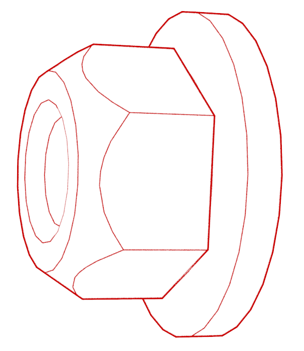
Remove the nuts that attach the charge port busbars to the charge port.
TIpUse of the following tool(s) is recommended:
- 10 mm deep socket
- ¼ in std flex head ratchet
- ¼ in torque wrench (installation only)
-
Release the charge port
manual release cable from the body clip.
-
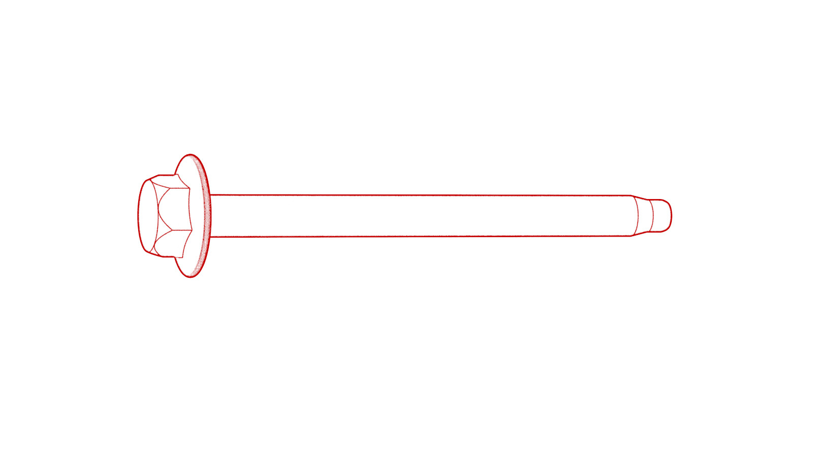
Remove the bolts that attach
the charge port to the body, and then remove the charge port from the
vehicle.
TIpUse of the following tool(s) is recommended:
- 10 mm deep socket
- Flex head ratchet/flex head torque wrench
Install
-
If reinstalling the same charge port, clean the charge port busbar HV header at the back of the charge port assembly with an IPA wipe, and then air dry for 1 minute.
NoteSkip this step if installing a new charge port assembly, as the new charge port has pre-applied electrical joint compound.TIpUse a plastic trim tool to push the IPA wipe into the crevices of the charge port busbar HV header.
-
Position the charge port in
the vehicle, and then install the bolts that attach the charge port to the
body.
 9 Nm (6.6 lbs-ft)TIpUse of the following tool(s) is recommended:
- 10 mm deep socket
- Flex head ratchet/flex head torque wrench
WarningMake sure the harness is routed out, and the adhesive pad with zip tie is properly mounted if it is installed. -
Secure the charge port
manual release cable in the body clip.
-
Use an IPA wipe to clean all
residue and debris from the charge port busbar leads, and then air dry for 1
minute.
WarningThe video(s) included in this procedure are meant as an overview for supplemental purposes only. Follow all of the steps listed in the procedure to avoid damage to components and/or personal injury.
-
If reinstalling the same
charge port, apply two drops of electrical joint compound on each of the
charge port busbar leads, on the side that makes contact with the charge
port.
NoteSkip this step if installing a new charge port assembly, as the new charge port has pre-applied electrical joint compound.
-
Position the charge port
busbars on the change port studs, and then install the nuts that attach the
busbars to the charge port.
 9 Nm (6.6 lbs-ft)TIpUse of the following tool(s) is recommended:
- 10 mm deep socket
- ¼ in std flex head ratchet
- ¼ in torque wrench (installation only)
- Put on HV insulating gloves and leather over gloves.
-
At the charge port, use the
Hioki resistance meter to measure the resistance between the charge port
busbar lead and the charge port busbar stud. Also perform this test on the
other lead and stud.
NoteThe acceptable resistance is between 0.050 mΩ (50 μΩ) and 0.270 mΩ (270 μΩ). If the measured resistance is above 0.270 mΩ (270 μΩ), there is too much resistance in the High Voltage joint. Remove the fastener, clean areas with isopropyl alcohol, install fastener back and test again, as appropriate.NoteIf the resistance is lower than 0.050 mΩ (50 μΩ), reposition the probes and measure again. If after 4 attempts the resistance is consistently lower than 0.050 mΩ (50 μΩ), the test has passed; continue to the next step.
-
Install the charge port
busbar fastener cover on the charge port assembly.
-
Connect the low voltage harness connectors (x2) on the charge port, and then install the locking tabs (x2) that secure the connectors.
NotePush the red locking tab into the connector to engage the connector lock.TIpCarefully insert the white locking tab in the 12-pin low voltage connector until it locks with the black connector tab.
- Connect the LH liftgate task light connector.
- Move LH trunk side trim back into position.
- Install the trunk garnish. See Garnish - Trunk (Remove and Replace).
- Install the trunk sill trim panel. See Trim - Sill - Trunk (Remove and Replace).
- Install the trunk floor trim. See Trim - Floor - Trunk (Remove and Replace).
- Reconnect 12V power. See 12V/LV Power (Disconnect and Connect).
-
Verify the operation of the
charging system:
NoteUse the customer's charging equipment, if present.CAUTIONDo not try to manually close the charge port door.TIpIf the charge port does not operate as expected or the vehicle does not charge, run TEST-RESET_CPvia Service Mode:High Voltage ➜ Charging ➜ Charge Port ECU resetvia Toolbox:(link)
- Move both front seats to their original positions.